Sample loading device

A technology of mounting seat and ball screw, which is applied in the direction of analyzing materials and instruments, can solve the problems of high repair and maintenance costs, uneven force, and affecting the service life of the device, so as to reduce repair and maintenance costs and ensure sealing performance , the effect of improving the service life

Active Publication Date: 2016-07-06
长沙开元仪器有限公司
View PDF4 Cites 0 Cited by
  • Summary
  • Abstract
  • Description
  • Claims
  • Application Information

AI Technical Summary

Problems solved by technology

[0004] However, due to the need to install two motors, its mechanism is limited, and the driving screw is located at the non-center position of the middle supporting plate, so that a moment arm is formed between the center of gravity of the middle supporting plate part and the screw mandrel, and thus a gravity moment is generated. , so that the verticality between the middle supporting plate and the screw rod will change greatly after a period of time, so that the middle supporting plate and the screw rod are no longer perpendicular
This will directly cause the furnace core to rotate in the furnace, because the gap between the furnace core and the furnace is very small, there will be a 'sweeping wall' phenomenon between the furnace core and the furnace, which will affect the service life of the device; and, it is necessary to install two Each motor separately drives the lifting and rotation of the sample, which makes the structure of the sample loading device complex and inconvenient to disassemble, and the repair and maintenance costs are high
In addition, because of the eccentricity of the mechanism after the sample is loaded, the force on the center plate is uneven, which can easily cause the sealing performance here to fail.

Method used


Image

  • Sample loading device
  • Sample loading device
  • Sample loading device

Examples


Embodiment Construction

[0055] The invention discloses a sample loading device to improve the service life of the device and reduce repair and maintenance costs.

[0056] The following will clearly and completely describe the technical solutions in the embodiments of the present invention with reference to the accompanying drawings in the embodiments of the present invention. Obviously, the described embodiments are only some, not all, embodiments of the present invention. Based on the embodiments of the present invention, all other embodiments obtained by persons of ordinary skill in the art without making creative efforts belong to the protection scope of the present invention.

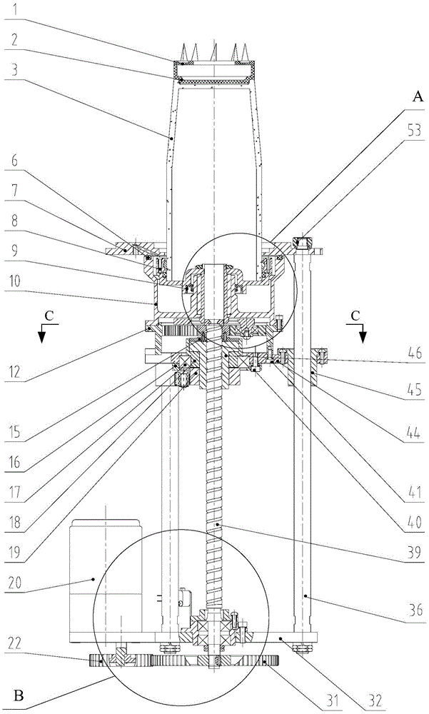
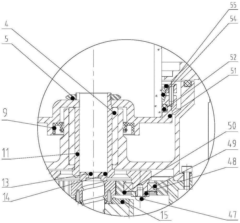
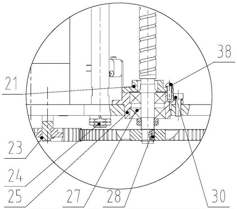
[0057] Please refer to Figure 1-Figure 3 , figure 1 Schematic diagram of the structure of the sample loading device provided by the embodiment of the present invention.

[0058] The embodiment of the present invention provides a sample loading device, including: a ball screw 39, the ball screw 39 is rotatably arranged on ...


PUM


Abstract

The invention discloses a sample feeding device, which comprises a ball screw, a motor, a ball screw nut, a mandrel, a bridge plate, a damping assembly, an installing seat, an upper cover, a furnace core, a transmission mechanism and a baffle plate, wherein the ball screw is rotationally arranged on a machine core fixing plate, the motor drives the ball screw to rotate, the ball screw nut is matched with the ball screw, one end of the mandrel is connected with the machine core fixing plate, the axial line of the mandrel is parallel to the axial line of the ball screw, the bridge plate is glidingly arranged on the mandrel, the damping assembly is arranged between the bridge plate and the ball screw nut, the installing seat is fixedly arranged on the bridge plate, the upper cover is arranged at one side, far away from the bridge plate, of the installing seat, the furnace core is rotationally arranged at one side, far away from the bridge plate, of the upper cover, the transmission mechanism is arranged on the ball screw in a sleeving way, and is connected with the furnace core, the baffle plate is arranged at one end, far away from the motor, of the ball screw, and is used for blocking the transmission mechanism, and the transmission mechanism is positioned between the ball screw nut and the baffle plate. The sample feeding device provided by the invention has the advantages that the service life of the device is prolonged, the repair and maintenance cost is reduced, and the hearth sealing reliability is ensured.

Description

technical field [0001] The invention relates to the technical field of conveying equipment, in particular to a sample loading device. Background technique [0002] At present, in the ash melting tester on the market, the sample is installed on the furnace core, the furnace core is installed on the middle support plate, and the middle support plate is fixedly connected with the screw screw mechanism through the screw nut. The first motor installed under the driving screw and away from the furnace drives the screw to rotate to realize the up and down movement of the middle supporting plate, so as to realize the loading and delivery of samples. [0003] After the sample is sent to the predetermined position in the furnace by the first motor, the second motor installed below the furnace and close to the furnace drives the sample to rotate in the furnace, so that the camera can observe through a fixed hole on the furnace to the test condition of the sample. [0004] However, du...

Claims


Application Information

Patent Timeline
Patent Type & Authority Patents(China)
IPC IPC(8): G01N35/10
Inventor 罗建文黄海键
Owner 长沙开元仪器有限公司
Why Eureka
Try Eureka