
Electric tool triggered by pressure

A technology for electric tools and work, which is applied in the direction of motor tools, manufacturing tools, and portable motorized devices. It can solve the problems of bit jumping, jumping, and inability to hold postures, etc., and achieves simplified actions, ingenious and novel structures, and reduced jumping. alignment effect

Inactive Publication Date: 2015-02-25
NANJING CHERVON IND
View PDF7 Cites 0 Cited by
  • Summary
  • Abstract
  • Description
  • Claims
  • Application Information

AI Technical Summary

Problems solved by technology

[0002] Existing electric tools, such as screwdrivers, etc., the user holds the tool with one hand and assists with the other hand during work. In order to control the work of the electric tool, a control button is often provided. The hand operates the control button while holding it. At this time, the user must release the thumb or forefinger of the holding hand and then touch the switch. It cannot always maintain a stable holding posture, so that the user is triggering the work. And when switching the working mode, the power tool will jump or move due to the loosening of the finger. Take the screwdriver as an example. After we hold the screwdriver, we need to align the screw and then turn it on. The action of turning on the finger needs to be released and then press the button. Finished. At this time, the bit may have jumped, and it is no longer accurately aligned with the screw. When screwing the screw, in the process of changing from loose to tight or from tight to loose, it may be necessary to switch the rotation power of the screwdriver, but if passed Release a finger to adjust, and it will cause the bit to jump

Method used


Image

  • Electric tool triggered by pressure
  • Electric tool triggered by pressure
  • Electric tool triggered by pressure

Examples


Embodiment Construction

[0033] The present invention will be specifically introduced below in conjunction with the accompanying drawings and specific embodiments.

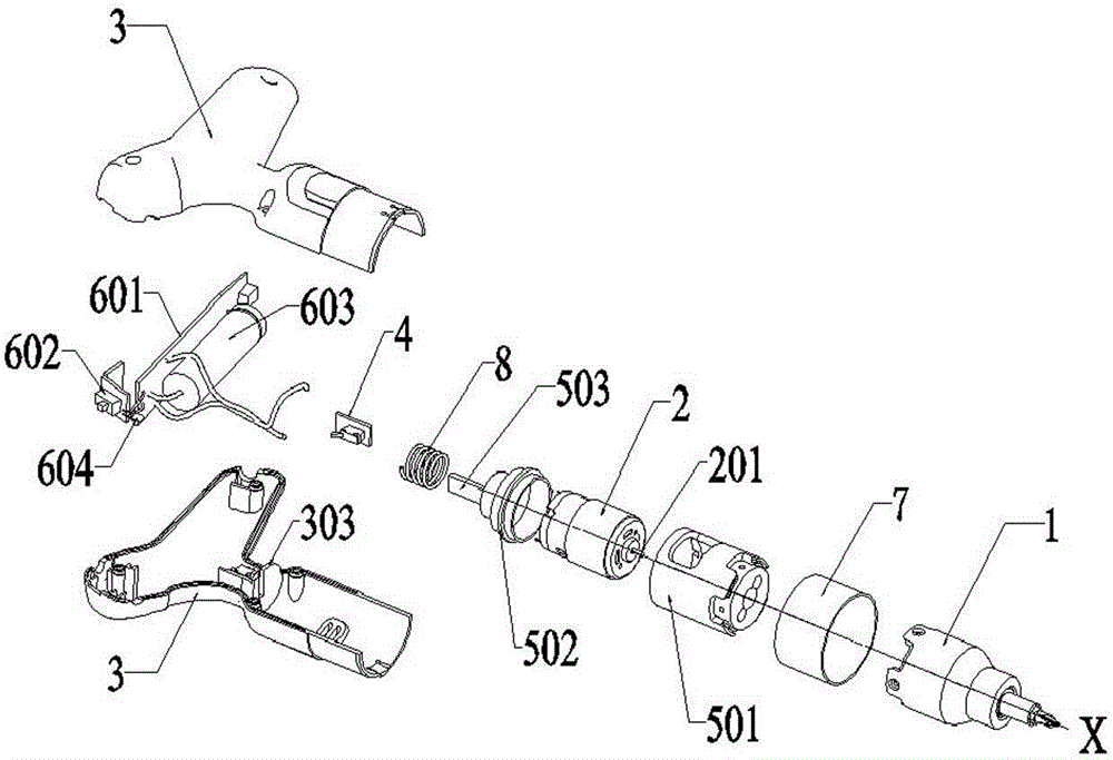
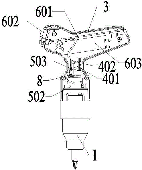
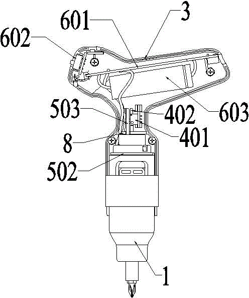
[0034] refer to Figure 1 to Figure 5 As shown, the electric tool of the present invention mainly includes: a working head 1, a motor 2, a handle housing 3, a trigger switch 4, a PCB board assembly, a first elastic member 8, an intermediate assembly, and the like.

[0035] Among them, the working head 1 is an executive mechanism for realizing functions, and is generally integrated with a transmission mechanism and tool accessories. The transmission structure is used to convert the power of the motor into a required form, and the tool accessories are used to realize specific functions. The motor 2 is used to drive the transmission structure of the working head 1. It should be noted that, in the present invention, the power supply for the motor 2 can be a battery or an external line connected to an external power supply. As a preference, in...


PUM


Abstract

The invention discloses an electric tool triggered by pressure. The electric tool comprises an operation head, a motor for driving the operation head, a handle shell, a triggering switch, an intermediate component and a first elastic member. One end of the intermediate component is used for triggering the switch, the other end of the intermediate component is used for mounting the operation head and the middle of the intermediate component is used for mounting the motor. The first elastic member is used for driving the intermediate component away from the triggering switch. A gripping part is formed at the top of the handle shell. A sleeve part with one open end is formed on the handle shell. The sleeve part is used for connecting and containing the intermediate component. The triggering switch is fixed inside the handle shell. The intermediate component is slidably connected with the handle shell. The electric tool triggered by pressure is novel and ingenious in structure, accords with ergonomics more, simplifies operational actions of the triggering motor during starting, and operational actions of triggering are combined with actions allowing alignment and pressing of the operation head, and the circumstance of misalignment caused by bouncing of the electric tool due to operation of the triggering motor is reduced.

Description

technical field [0001] The invention relates to an electric tool, in particular to an electric tool which is triggered to start working by applying pressure from a human hand. Background technique [0002] Existing electric tools, such as screwdrivers, etc., when working, the user holds the tool with one hand and assists with the other hand. In order to control the work of the electric tool, a control button is often provided. The hand operates the control button while holding it. At this time, the user must release the thumb or forefinger of the holding hand and then touch the switch. It cannot always maintain a stable holding posture, so that the user is triggering the work. And when switching the working mode, the power tool jumps or moves due to the loosening of the finger. Take the screwdriver as an example. After we hold the screwdriver, we need to align the screw and then turn it on. The action of turning on the finger needs to be released and then press the button F...

Claims


Application Information

Patent Timeline
Patent Type & Authority Patents(China)
IPC IPC(8): B25B21/00B25F5/00
Inventor 魏淦章智叶健戴长玺
Owner NANJING CHERVON IND
Learn More