
Brake measuring tape

A technology of tape measure and brake part, which is applied to bendable rulers, measuring devices, instruments, etc., can solve the problems of low braking effect and short service life of tape measure, and achieve the advantages of simple structure, low manufacturing cost and long service life Effect

Active Publication Date: 2012-12-19
胡兆贤
View PDF5 Cites 11 Cited by
  • Summary
  • Abstract
  • Description
  • Claims
  • Application Information

AI Technical Summary

Problems solved by technology

[0004] The invention provides a brake tape measure, which is used to solve the problems of low braking effect and short service life of the tape measure in the prior art due to the friction between the brake button and the tape measure tape to realize the braking function of the tape measure tape

Method used


Image

  • Brake measuring tape
  • Brake measuring tape
  • Brake measuring tape

Examples


Embodiment 1

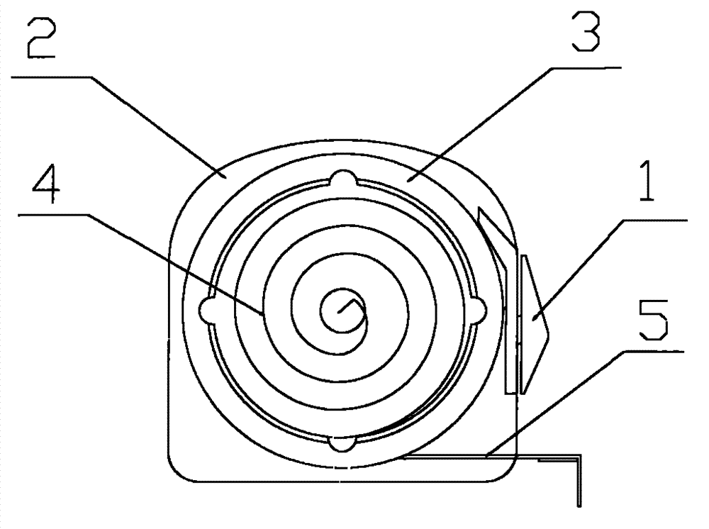
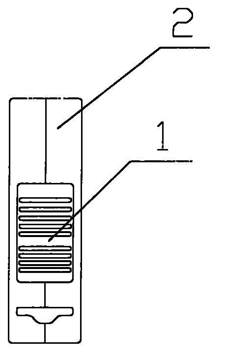
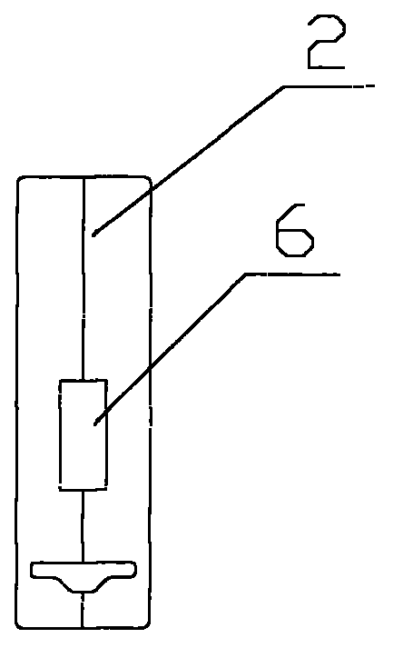
[0025] figure 1 Shown is a schematic structural view of a brake tape provided by Embodiment 1 of the present invention, including: a tape measure housing 2 , a spring box 3 , a spring 4 and a tape measure belt 5 installed in the tape measure housing 2 . Wherein, the tape measure band 5 is wound in the spring box 3, and the spring 4 is arranged inside the spring box 3; when the tape measure band 5 is pulled out, if the spring box 3 is not in contact with other objects, the reaction force of the spring 4 makes the spring box 3 turn in the tape measure housing 2 to retract the tape measure band 5 back into the spring case 3 in the tape measure housing 2. figure 2 for figure 1 right side view of the , image 3 for will figure 2 The view obtained after removing the brake button 1 in , such as figure 2 and image 3 As shown, in the brake tape measure, a brake button slot 6 is provided on one side of the tape measure housing 2 , and there is also a brake button 1 installed in...

Embodiment 2

[0032] Figure 5 Shown is a schematic structural diagram of a brake tape provided in Embodiment 2 of the present invention, Figure 6 for Figure 5 right side view of the , Figure 7 for will Figure 6 The view obtained after removing the brake button 11 in .

[0033] Similar to Example 1, such as Figure 5 to Figure 7 As shown, the brake tape provided by this embodiment includes: tape housing 2, spring box 8, spring ( Figure 5 not shown in, its structure is similar to image 3 ), tape measure tape 5 and brake button 11, wherein, Figure 5 to Figure 7 neutralize figure 1 The components with the same reference numerals have the same structure and function as described in Embodiment 1, similar to Embodiment 1: the tape measure tape 5 is wound in the spring case 8, and the spring is arranged inside the spring case 8. When the tape measure tape 5 When being pulled out, if spring case 8 does not contact with other objects, then the reaction force of spring makes spring case ...


PUM


Abstract

The invention provides a brake measuring tape, which comprises a measuring tape shell, a spring box arranged inside the measuring tape shell, a spring and a tape band, wherein the tape band is wound in the spring box; the spring is used for withdrawing the pull-out tape band into the spring box when the spring box does not contact a brake button; a brake button neck is arranged at one side of the measuring tape shell; a brake button is arranged inside the brake button neck; the brake button is arranged at a first preset position of the brake button neck when the tape band is pulled out, so as to contact and fix the spring box, so that the pulled tape band is not withdrawn into the spring box. The brake measuring tape provided by the invention is long in service life, high in reliability, simple in structure, low in manufacture cost, and strong in applicability.

Description

technical field [0001] The invention relates to the field of length measuring tools, in particular to a brake tape measure. Background technique [0002] As a length measuring tool, the tape measure has been welcomed by workers from all walks of life because of its small size, ease of use and portability. Wherein, brake tape measure is a kind of tape measure that uses more widely at present. [0003] The brake tape in the prior art generally includes a scale case, a scale tape arranged in the scale case, and a spring box for fixing the scale tape, and also includes a brake component for realizing the braking function, specifically, The existing brake tape is directly rubbed against the tape by braking parts such as the brake button and the tape to achieve the effect of fixing the tape. Obviously, there is a long time between the brake button of the existing brake tape and the tape The friction of the tape will easily cause the value of the tape measure to be rubbed off, an...

Claims


Application Information

Patent Timeline
Patent Type & Authority Applications(China)
IPC IPC(8): G01B3/10G01B5/02
Inventor 胡兆贤
Owner 胡兆贤
Learn More