Automatic measuring device for diameter of bearing ring

An automatic measurement and bearing ring technology, applied in the direction of mechanical diameter measurement, etc., can solve the problems of needing replacement, high production requirements, difficult installation and debugging, etc., to achieve the effect of easy installation, no debugging, and less difficulty in production

Active Publication Date: 2012-12-19
NINGBO ZHUANGHONGYI BEARING
View PDF6 Cites 16 Cited by
  • Summary
  • Abstract
  • Description
  • Claims
  • Application Information

AI Technical Summary

Problems solved by technology

This device has the following disadvantages: 1. The double probes must correspond to the rings of the bearing model one by one. When measuring different rings, the measuring blocks need to be replaced.
2 The measuring block requires that the three measuring heads are all on the same plane during the working measurement. Therefore, the production requirements of the measuring block are relatively high, and the installation and debugging are difficult

Method used


Image

  • Automatic measuring device for diameter of bearing ring
  • Automatic measuring device for diameter of bearing ring
  • Automatic measuring device for diameter of bearing ring

Examples


Embodiment 1

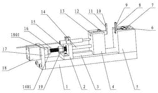
[0026] Example 1: Automatic measuring device for outer finger bearing ring diameter

[0027] Such as figure 1 , 2 As described in and 3, the bearing ring diameter automatic measuring device includes a base plate 1, a fixed measuring seat 5, a dynamic measuring slide 4, a slide rail 3, a measuring mechanism and a measuring pen.

[0028] One end of the base plate 1 is fixedly provided with a fixed measuring seat 5, and two limiting grooves II6 are arranged on the fixed measuring seat 5, and the two limiting grooves II6 form a V-shaped structure, and the bisector of the angle formed by the two limiting grooves II6 and the sliding The rails 3 are in the same straight line direction, and the head of the V-shaped structure points to the dynamic measuring slide 4. The bottom of each limiting groove II6 is provided with a screw hole for fixing a fixed measuring block, and a fixed measuring block is arranged in the limiting groove II6. The measuring block includes a measuring rod 8 ...

Embodiment 2

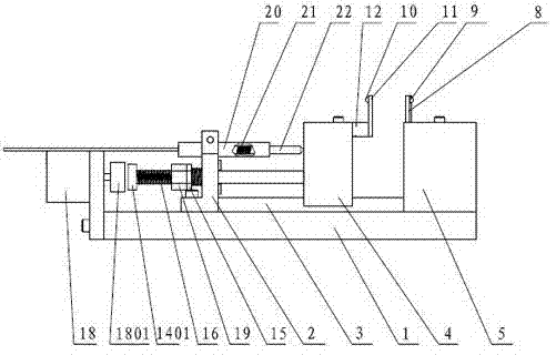
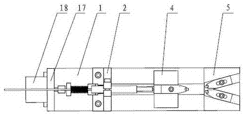
[0038] Example 2: Automatic measuring device for inner finger of bearing ring diameter

[0039] Such as Figure 4 , 5 As described in and 6, the bearing ring diameter automatic measuring device includes a base plate 1, a fixed measuring seat 5, a dynamic measuring slide 4, a slide rail 3, a measuring mechanism and a measuring pen.

[0040] One end of the base plate 1 is fixedly provided with a fixed measuring seat 5, and two limiting grooves II6 are arranged on the fixed measuring seat 5, and the two limiting grooves II6 form a V-shaped structure, and the bisector of the angle formed by the two limiting grooves II6 and the sliding The rails 3 are in the same straight line direction, and the head of the V-shaped structure points to the dynamic measuring slide 4. The bottom of each limiting groove II6 is provided with a screw hole for fixing a fixed measuring block, and a fixed measuring block is arranged in the limiting groove II6. The measuring block includes a measuring ro...


PUM


Abstract

The invention relates to an automatic measuring device for a diameter of a bearing ring and belongs to the technical field of a measuring device for a shaft sleeve ring. The automatic measuring device comprises a base plate and further comprises a fixed measuring base, a moveable measuring slide base, a measuring mechanism and a measuring pen which are arranged on the base plate, wherein the moveable measuring slide base is in sliding fit with a slide rail arranged on the base plate; a moveable measuring block is arranged on the moveable measuring slide base; a moveable measuring head is arranged on the moveable measuring block; a pair of independent fixed measuring blocks is arranged on the fixed measuring base; and a fixed measuring head is arranged on the fixed measuring blocks. The automatic measuring device for the diameter of the bearing ring is low in manufacturing demand on the measuring blocks, is simply mounted, is free from debugging and has a generality within a certain scope.

Description

technical field [0001] The invention belongs to the technical field of measuring devices for shaft sleeve rings, in particular to an automatic measuring device for diameters of bearing rings. Background technique [0002] Bearings require high precision, so the inner diameter and channel diameter of the inner ring and the outer diameter and channel diameter of the outer ring need to be precisely measured. The existing automatic bearing ring diameter measuring device includes a single measuring head block and a double measuring head block with two measuring heads fixed on the same measuring block, driven by a cylinder and a spring structure, and one of the measuring blocks is driven by the spring The change in position distance for linear or arcuate motion calculates the ferrule diameter. This device has the following disadvantages: 1. The double probes must correspond to the rings of the bearing type one by one. When measuring different rings, the measuring blocks need to b...

Claims


Application Information

Patent Timeline
Patent Type & Authority Applications(China)
IPC IPC(8): G01B5/08G01B5/12
Inventor 张惠邦
Owner NINGBO ZHUANGHONGYI BEARING
Why Eureka
Try Eureka