Same floor draining joint for building

A technology for same-layer drainage and drainage interface, which is applied in buildings, water supply installations, indoor sanitary pipeline installations, etc., and can solve the problems of unable to discharge ground water, accumulated water that cannot be safely drained, and floor drains that cannot be installed

Inactive Publication Date: 2012-12-26
KUNMING QUNZHIYING TECH
View PDF7 Cites 36 Cited by
  • Summary
  • Abstract
  • Description
  • Claims
  • Application Information

AI Technical Summary

Problems solved by technology

[0002] At present, floor drains cannot be installed when the same layer is discharged using the method of non-falling slabs, and the ground water cannot b

Method used


Image

  • Same floor draining joint for building
  • Same floor draining joint for building
  • Same floor draining joint for building

Examples


Embodiment 1

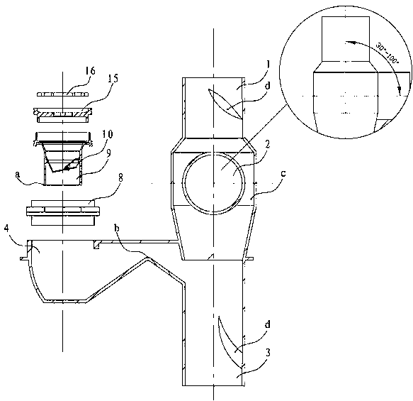
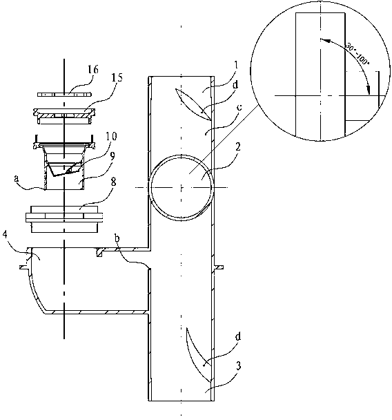
[0029] Such as Figure 1-4 The building drainage joint on the same floor as shown in the present invention is composed of an upper riser drainage interface 1, a lower riser drainage interface 3 and at least two horizontal pipe drainage interfaces 2, 4. The upper riser drainage interface 1 and the lower riser The upper and lower ends of the drainage interface 3 are connected, and the positions between at least two horizontal pipe drainage interfaces are staggered from each other and are located between the upper vertical pipe drainage interface 1 and the lower vertical pipe drainage interface. The direction of the drainage interface 1 of the upper riser is the same or nearly the same, and the angle between the direction of the inlet of at least one drainage interface 2 of the horizontal pipe and the direction of the drainage interface 1 of the upper riser is between 30° and 100°. The bottom of the horizontal pipe drainage interface 4 with the same or nearly the same orientation...

Embodiment 2

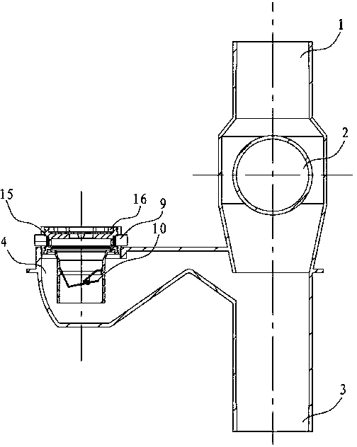
[0031] Such as Figure 5-10 As shown, in the building drainage joint on the same floor according to the present invention, there is a pipe section 8 under the cover plate 16, and the pipe section 8 is sealed and connected with the horizontal pipe drainage interface 4 facing the same direction as the upper riser drainage interface 1, and the water sealing device 9 In the pipe section 8, the water sealing device 9 and the pipe section 8 are separated from each other. The pipe section 8 is provided with one or more drainage inlets 5, 6. The cover plate 16 is detachable from the lower end pipe section. There is an inner sleeve 13, 14 in the pipe section 8 below the cover plate 16 and above the water sealing device 9, and the inner sleeve 13 is connected to the water sealing device 9. The inner sleeve 14 is located below the cover plate 16. There is a handle 15 between the inner sleeve 15 and the cover plate 16. The water seal device 9 is detachable from the horizontal pipe draina...

Embodiment 3

[0033] Such as Figure 5-10 As shown, in the building same-floor drainage joint according to the present invention, below the drainage inlets 5, 6 of the pipe section 8 and the inner sleeve drainage inlet 12, and above the drainage outlet of the water sealing device 9, a filter device 11 is provided; There is no inner sleeve drainage inlet on the inner sleeve corresponding to the drainage inlet 6, and the end of the pipe section drainage inlet 6 is provided with a filter head 7, and the filter head 7 is a joint provided with small holes, and a pipe section drainage outlet 6 is provided with one or one Above filter head 7. All the other are with embodiment 2.


PUM


Abstract

The invention relates to a same floor draining joint for a building, in particular to a same floor draining joint for a toilet, which consists of an upper vertical pipe draining port, a lower vertical pipe draining port and at least two transverse pipe draining ports; the upper vertical pipe draining port is communicated with the upper end and the lower end of the lower vertical pipe draining port; the at least two transverse pipe draining ports are staggered in position and are arranged between the upper vertical pipe draining port and the lower vertical pipe draining port; the orientation of the inlet of at least one of the transverse pipe draining ports is equal to or nearly equal to the orientation of the upper vertical pipe draining port, and the orientation of the inlet of at least one of the transverse pipe draining ports forms an included angle of 30-100 degrees with the orientation of the upper vertical pipe draining port. The same floor draining joint is rational and scientific in structure, and is capable of realizing the same floor draining and the same floor maintenance when the draining joint is adopted in the same floor draining of the non-falling plate or falling plate; the draining is more safe; the water is not easy to accumulate in the falling plate layer even the way of the falling plate is adopted, and the accumulated water is safely and completely discharged, so as to avoid the foreign smell in the room.

Description

technical field [0001] The invention relates to a same-floor drainage joint for buildings, in particular to a same-floor drainage joint for toilets. Background technique [0002] At present, floor drains cannot be installed when the same layer is discharged using the method of non-falling slabs, and the ground water cannot be discharged. Generally, floor drains are installed on local slabs to solve the discharge of ground water. The safe discharge is clean, making the room prone to odors. Contents of the invention [0003] The purpose of the present invention is to overcome the existing technical defects, and to provide a toilet that can safely discharge ground water without any lowering board when using the same layer of drainage without lowering boards, and can safely drain the lowering board layer when using the same layer of lowering boards to drain water It is a kind of drainage joint on the same floor of the building that accumulates water in the room so that th...

Claims


Application Information

Patent Timeline
IPC IPC(8): E03C1/122E03C1/28E03C1/288
Inventor 林国强邱寿华
Owner KUNMING QUNZHIYING TECH
Why Eureka
Try Eureka