
A side-wall ventilation drainage system

A drainage system and side wall technology, applied in the field of building water supply and drainage, can solve the problems of multi-pipe space, limited drainage capacity of drainage risers, uneconomical, etc., and achieve the effect of satisfying drainage needs and improving ventilation and drainage capacity.

Inactive Publication Date: 2019-09-27
民航机场规划设计研究总院有限公司
View PDF5 Cites 0 Cited by
  • Summary
  • Abstract
  • Description
  • Claims
  • Application Information

AI Technical Summary

Problems solved by technology

[0003] However, drain risers with sidewall venting have very limited drainage capacity
According to previous design experience, in the area with high passenger density in the terminal building, the drainage design flow rate of a single toilet can reach 5L / s. When toilets on different floors share the same drainage riser, only the drainage riser for side wall ventilation is provided. The drainage capacity cannot meet the drainage demand, so it is necessary to set up multiple drainage risers to discharge sewage in layers. This method is uneconomical and requires more pipe space
In addition, due to the large amount of space above the terminal building, there are also very high requirements for the integrity of the roof, so it is not suitable to set up the roof ventilation

Method used


Image

  • A side-wall ventilation drainage system

Examples


Embodiment Construction

[0028] The core of the present invention is to provide a side wall ventilation and drainage system, which improves the drainage capacity on the basis of not occupying too much space and destroying the inner appearance and integrity of the building.

[0029] The following will clearly and completely describe the technical solutions in the embodiments of the present invention with reference to the accompanying drawings in the embodiments of the present invention. Obviously, the described embodiments are only some, not all, embodiments of the present invention. Based on the embodiments of the present invention, all other embodiments obtained by persons of ordinary skill in the art without making creative efforts belong to the protection scope of the present invention.

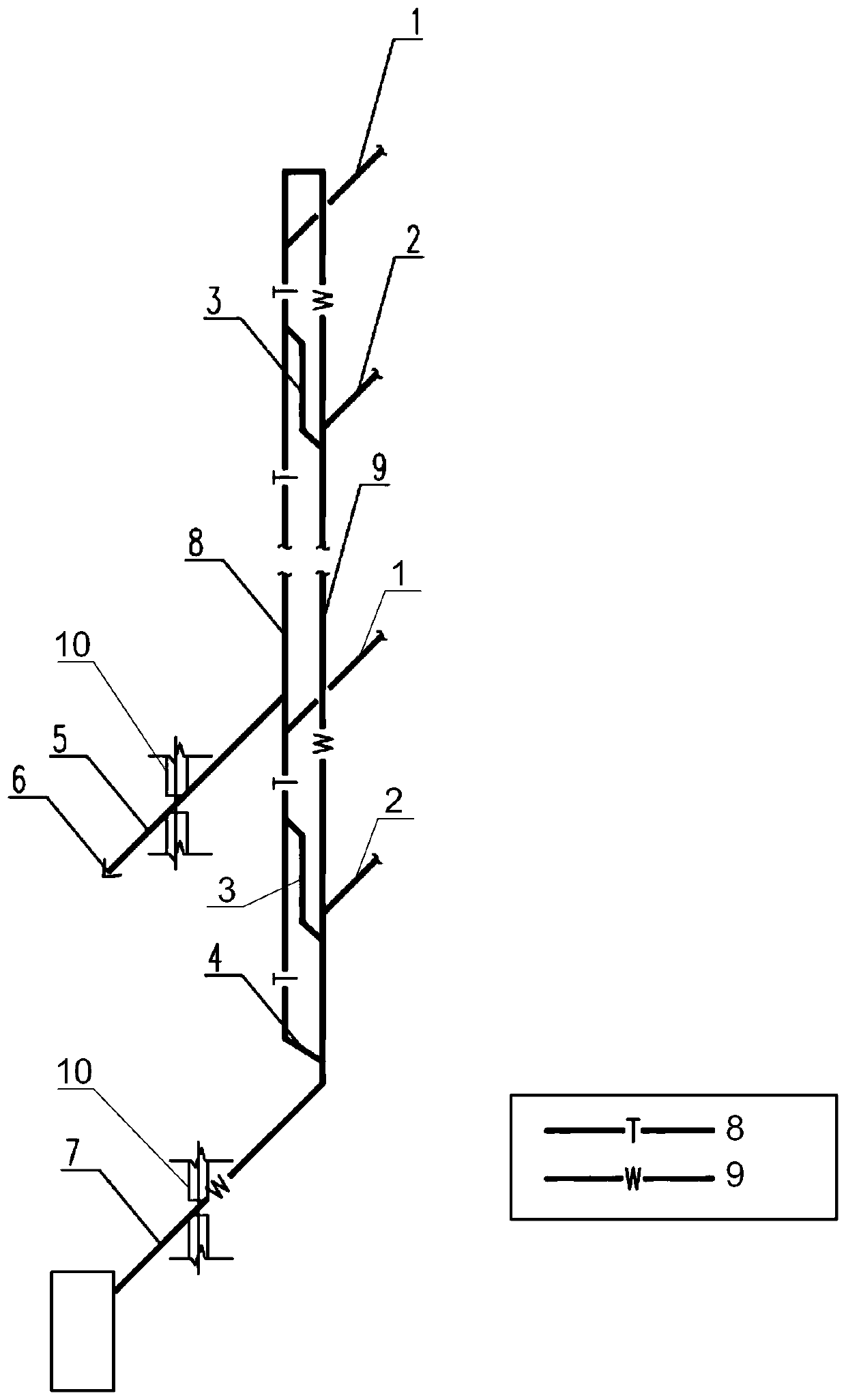
[0030] Please refer to figure 1 , the embodiment of the present invention provides a side wall ventilation and drainage system, which includes a ventilation system and a drainage system. The drainage system includ...


PUM


Abstract

The application discloses a side wall ventilation drainage system, comprising a draining standpipe, draining transverse branch-pipes, a ventilation standpipe, combination ventilation pipes, circular ventilation pipes, a side wall ventilation pipe and side wall ventilation caps; drainage points on each floor separately communicate with the draining standpipe through the corresponding draining transverse branch-pipe; the tops of the ventilation standpipe and the draining standpipe communicate with each other within the ceiling of a highest floor, and the bottom ends of the ventilation standpipe and the draining standpipe communicate with each other under the ground of a lowest floor; the ventilation standpipe and the draining standpipe communicate with each other in each floor through the combination ventilation pipes; the circular ventilation pipes communicating with the ventilation standpipe are arranged in the ceilings of all the floors; the side wall ventilation pipe is arranged in the ceiling of the lowest floor and communicates with the ventilation standpipe, and the side wall ventilation pipe stretches out the facade of a side wall; and the side wall ventilation cap is connected at one end, where the side wall ventilation pipe stretches out the facade, of the side wall. The ventilation drainage system of the side wall combines the advantages of self-circulation ventilation and extending-to-roof ventilation of a main ventilation standpipe so as to be able to effectively balance the pressure of the standpipe and increase the drainage flow of the standpipe and present such characteristics as easy concealing, beauty and simple maintenance and no demand for special pipe fittings.

Description

technical field [0001] The invention relates to the technical field of building water supply and drainage, in particular to a side wall ventilation and drainage system. Background technique [0002] Large public buildings such as terminal buildings usually have the characteristics of large building volume and low building height. In addition, in order to achieve a transparent visual effect inside the terminal building, the departure floor often adopts a floor height of more than eight meters, and the internal rooms are mostly in the form of a room within a room, and the outside of the terminal building is almost entirely covered by glass curtain walls. Therefore, in order not to damage the interior look and feel of the building, there is almost no condition to install a ventilating standpipe. The drainage and ventilation needs of this type of building are met by the side wall ventilation. [0003] However, drainage risers with sidewall venting have very limited drainage cap...

Claims


Application Information

Patent Timeline
IPC IPC(8): E03C1/122
CPCE03C1/122E03C1/1222
Inventor 李琛吴熙申延波
Owner 民航机场规划设计研究总院有限公司
Learn More