Gas collection tank for gas extraction and gas collecting and water discharging device for gas extraction

A gas and gas box technology, which is applied in the fields of gas pumping and collecting gas boxes and gas pumping and collecting gas and water discharge devices, can solve the problems that the drainage capacity of the drainage device cannot meet the requirements, etc.

Pending Publication Date: 2019-10-25
永煤集团股份有限公司新桥煤矿
View PDF3 Cites 0 Cited by
  • Summary
  • Abstract
  • Description
  • Claims
  • Application Information

AI Technical Summary

Problems solved by technology

[0005] The purpose of the present invention is to provide a gas collection box for gas extraction, which is used to solve the problem that the drainage capacity of the drainage device cannot meet the requirements when the water volume in the existing extraction branch pipe is large
Another object of the present invention is to provide a gas collection and discharge device for gas extraction, which is used to solve the problem that the drainage capacity of the drainage device cannot meet the requirements when the water volume in the existing extraction branch pipe is large

Method used


Image

  • Gas collection tank for gas extraction and gas collecting and water discharging device for gas extraction
  • Gas collection tank for gas extraction and gas collecting and water discharging device for gas extraction
  • Gas collection tank for gas extraction and gas collecting and water discharging device for gas extraction

Examples


Embodiment Construction

[0043] Embodiments of the present invention will be further described below in conjunction with the accompanying drawings.

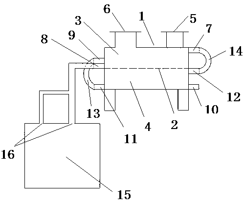
[0044] A specific embodiment of the gas pumping gas collection and water release device of the present invention, as figure 1 As shown, the gas collection and release device for gas pumping includes an automatic water release device 15 and a gas collection tank for gas pumping. The automatic water release device 15 can collect liquid through the water discharge device water inlet 16, and realize the accumulation of water after the liquid inside it reaches a set height. Automatic discharge, the automatic water release device 15 has two water release device water inlets 16, and the two water release device water inlets 16 are jointly connected with the automatic water outlet 8. The structure of the automatic water release device 15 is a common structure in the prior art, and will not be repeated here repeat.

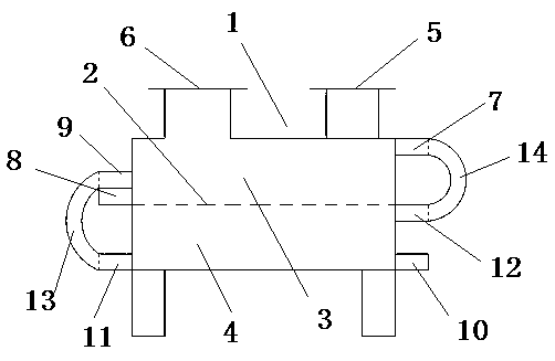
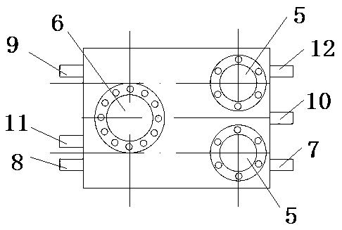
[0045] like figure 2 and image 3 As shown...


PUM


Abstract

The invention relates to a gas collection tank for gas extraction and a gas collecting and water discharging device for gas extraction. The gas collection tank for gas extraction comprises a gas and water separation tank and a water storage tank, wherein a water discharging port and a water tank water inlet are formed in the water storage tank; an automatic water discharging port and a manual water discharging port are formed in the gas and water separation tank, the manual water discharging port is connected with the water tank water inlet of the water storage tank, and a water feeding stop valve is arranged on a water tank water feeding pipeline; and a separation tank gas guide port is further formed in the top of the gas and water separation tank, a water tank gas guide port is formed in the top of the water storage tank, and the separation tank gas guide port is connected with the water tank gas guide port through a water tank gas guide pipeline. When the volume of solid-liquid mixtures in the water storage tank reaches a certain value, a water discharging valve is turned on, the solid-liquid mixtures in the water storage tank are discharged from the water storage tank throughthe water discharging valve, and accordingly, the gas collection tank for gas extraction can meet the water discharging requirement of the gas and water separation tank when the mixtures in a branch extraction pipe contain too much liquid and solids. Besides, gas extraction does not need to be stopped during water discharging of the gas and water separation tank and the water storage tank, operation is convenient, and the extraction efficiency is enhanced.

Description

technical field [0001] The invention relates to a gas collection box for gas pumping and a gas collection and discharge device for gas pumping. Background technique [0002] During the gas drainage process, the gas drainage borehole is affected by the cracks in the coal seam roof and floor. During the drainage process, the water and coal dust in the borehole will enter the main pipeline along the extraction branch pipe. Because the diameter of the main pipeline is relatively thick, If the gas flow rate in the pipe is slow, water and coal dust will settle in the main pipe, causing blockage of the main pipe and affecting normal gas extraction. [0003] In order to solve the problem of blockage of the main pipeline due to the water and coal in the borehole flowing into the main pipeline, there are drainage devices suitable for gas drainage conditions in the prior art. The announcement date is November 09, 2018, which discloses the technical scheme of using a water collection t...

Claims


Application Information

Patent Timeline
Patent Type & Authority Applications(China)
IPC IPC(8): E21F7/00E21F16/00
CPCE21F7/00E21F16/00
Inventor 宋正国徐恒恒张茂宇李少华刘林朱森卓勤源余祥峰代海锋游春林张洋王江龙
Owner 永煤集团股份有限公司新桥煤矿
Why Eureka
Try Eureka