Flush ring of squatting pan with touch flush valve
A squatting toilet and flush valve technology, applied in the field of flushing ring, can solve the problems of large resistance and long flushing ring pipeline, and achieve the effects of high impact force on the waterway, clean flushing, and strong waterway force.
Inactive Publication Date: 2012-12-26
CHONGQING XINJIE ENVIRONMENTAL PROTECTION TECH
View PDF0 Cites 1 Cited by
- Summary
- Abstract
- Description
- Claims
- Application Information
AI Technical Summary
Problems solved by technology
The technical problem to be solved by the flushing ring with a touch-sensitive flushing valve squatting pan of the present invention is to solve the defects of long pipes and high resistance of the flushing ring, and provide a water circuit with a large impact force, clean flushing, and water-saving flush ring
Method used
View moreImage
Smart ImageViewing Examples

Examples
Embodiment Construction
Login to View More PUM
 Abstract
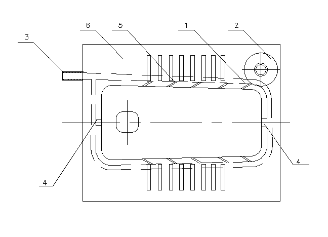
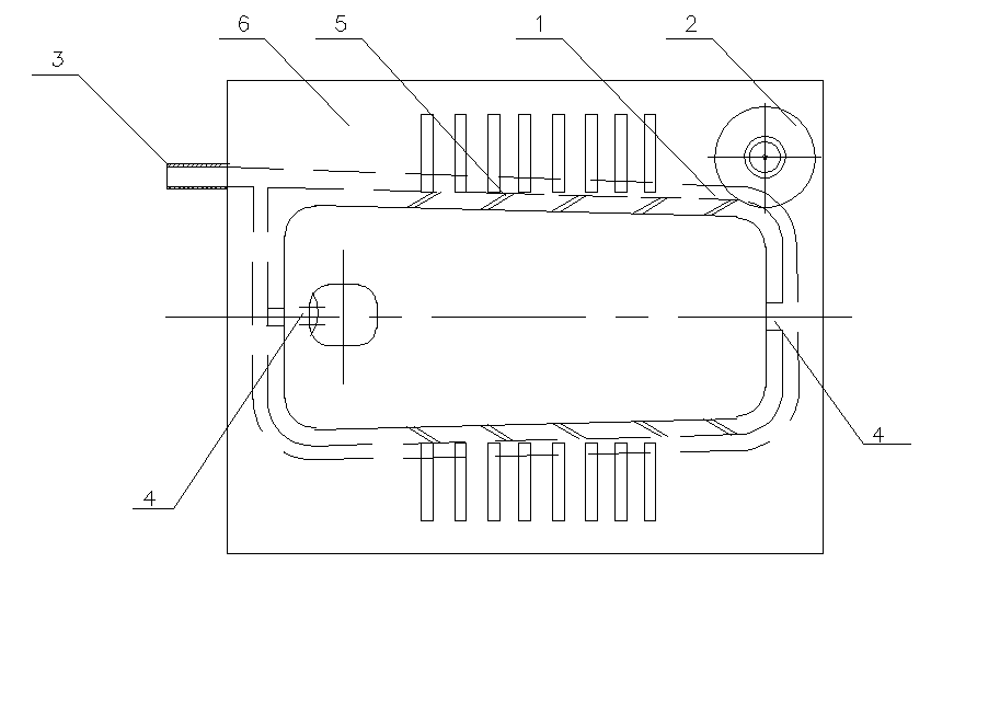
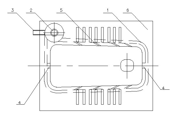
The invention relates to the technical field of bathroom water path arrangement, in particular to a flush ring of a squatting pan with a touch flush valve. The flush ring is arranged in the main body of the squatting pan, the touch flush valve is arranged on the flush ring channel, and the water inlet of the flush ring is arranged at the side edge of the main body of the squatting pan. With the inventive technical scheme, as the water inlet of the flush ring is arranged at the side edge of the main body of the squatting pan, the water ring distance from the water inlet to a main water outlet of the flush ring is reduced, compared with prior arts where the water inlet of the flush ring is arranged in the middle part of the front end or the rear end of the squatting pan, at least two corners are reduced, resistance in flushing process is reduced, the impact force of water is ensured to facilitate flushing of sewage, flushing times is reduced, and water consumption is saved. In addition, as the water inlet is arranged at the side edge of the main body of the squatting pan, impact forces of water flows on two sides are inconsistent, to form a swirling effect, which further facilitates flushing of sewage cleanly.
Description
technical field [0001] The invention relates to the technical field of bathroom waterway arrangement, in particular to a flush ring with a touch-sensitive flush valve squatting pan. Background technique [0002] The traditional squatting pan sold on the market is used in most families and public places. The dirt is mostly concentrated in the front part of the squatting pan toilet, and the sewage outlet is arranged at the rear part of the squatting pan toilet. The water inlets are all set at the middle part of the rear end of the squatting pan body, and the main water outlet is set at the middle part of the front end of the squatting pan body. Divided into two paths, passing through the rear corner, then passing through the side, then passing through the front corner, and finally flushing out at the main water outlet of the flushing ring; with such a flushing ring structure, when the flushing valve is opened, water flows into the inlet water through the valve The pipe then ...
Claims
Login to View More Application Information
Patent Timeline
 IPC IPC(8): E03D11/04
Inventor 邓严
Owner CHONGQING XINJIE ENVIRONMENTAL PROTECTION TECH
Features
- R&D
- Intellectual Property
- Life Sciences
- Materials
- Tech Scout
- Unparalleled Data Quality
- Higher Quality Content
- 60% Fewer Hallucinations
Learn More Browse by: Latest US Patents, China's latest patents, Technical Efficacy Thesaurus, Application Domain, Technology Topic, Popular Technical Reports.
© 2025 PatSnap. All rights reserved.Legal|Privacy policy|Modern Slavery Act Transparency Statement|Sitemap|About US| Contact US: help@patsnap.com