Supercharge Your Innovation With Domain-Expert AI Agents!

Engine oil bottom shell structure

A technology of engine oil and shell structure, applied in the direction of engine components, machine/engine, engine lubrication, etc., can solve the problems of high noise, insufficient strength, rigidity, poor performance, etc., to reduce noise, reduce weight, and improve strength Effect

Active Publication Date: 2015-05-06
DONGFENG MOTOR CORP HUBEI
View PDF5 Cites 0 Cited by
  • Summary
  • Abstract
  • Description
  • Claims
  • Application Information

AI Technical Summary

Problems solved by technology

Thin-walled parts usually perform poorly in terms of NVH, and their strength and rigidity are slightly insufficient, and the oil baffle in the prior art is installed on the outer boss of the oil sump casing, and it is impossible to install and position the oil baffle. Therefore, it is urgent to design an engine oil pan structure with better performance and the ability to install and fix the oil baffle

Method used


Image

  • Engine oil bottom shell structure
  • Engine oil bottom shell structure
  • Engine oil bottom shell structure

Examples


Embodiment Construction

[0013] The present invention will be further described below in conjunction with accompanying drawing:

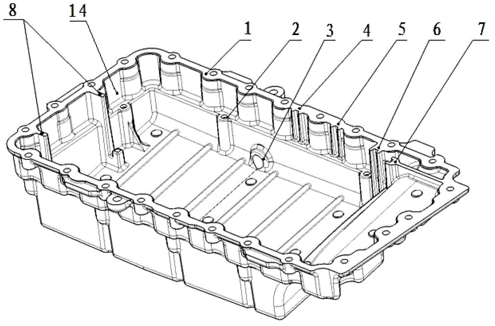
[0014] Such as figure 1 As shown, the present invention includes an oil sump case 14, an outer boss is arranged on the outer edge of the top of the oil sump case 14, a bolt hole is provided on the first flange surface 1 of the outer boss, and the inner wall of the oil sump case 14 There is an inner boss on the top, the inner boss is lower than the outer boss, there are bolt holes on the second flange surface of the inner boss, the oil pan between the inner boss and the outer boss A positioning structure is provided on the inner wall of the body 14 . The positioning structure includes a third positioning structure 4 and a fourth positioning structure 5. The third positioning structure 4 and the fourth positioning structure 5 are two groove structures that are recessed toward the inner wall of the oil sump shell, and are located in the same position as the oil sump shell 14....


PUM


Abstract

The invention relates to an engine oil bottom shell structure, and belongs to the technical field of automobile power devices. The engine oil bottom shell structure comprises an oil bottom shell, wherein the outer edge of the top of the oil bottom shell body is provided with an outer layer boss, and a first flange face of the outer layer boss is provided with a bolt hole; the inner wall of the oil bottom shell body is provided with an inner layer boss, and the inner layer boss is not lower than the outer layer boss; and a second flange face of the inner layer boss is provided with a bolt hole, and the inner wall of the oil bottom shell body arranged between the inner layer boss and the outer layer boss is provided with a localization structure. The engine oil bottom shell structure provided by the invention has an installation function of the oil baffle plate, is provided with the localization structure of the specific oil baffle plate, can provide an installation position of the oil baffle plate, meanwhile, greatly improve the intensity and rigidity of an oil bottom shell, and reduce a radiating area; the oil bottom shell is of a layered structure so as to be beneficial to reduce noises. In addition, the engine oil bottom shell structure is an aluminium alloy die casting and can lighten weight, and the larger intensity rigidity is obtained.

Description

technical field [0001] The invention belongs to the technical field of automobile power devices, and in particular relates to an engine oil pan structure. Background technique [0002] Most of the current engine oil pans are stamped thin-walled parts, which are mainly used to store engine oil and protect the internal moving parts of the engine. Thin-walled parts usually perform poorly in terms of NVH, and their strength and rigidity are slightly insufficient, and the oil baffle in the prior art is installed on the outer boss of the oil sump casing, and it is impossible to install and position the oil baffle. The noise is louder, so it is urgent to design an engine oil pan structure with better performance and the ability to install and fix the oil baffle. Contents of the invention [0003] The purpose of the present invention is to address the above defects and provide an engine oil pan structure that can not only provide the installation position of the oil baffle, but a...

Claims


Application Information

Patent Timeline
Patent Type & Authority Patents(China)
IPC IPC(8): F01M11/00
Inventor 樊红磊刘明涛田宁周洪光
Owner DONGFENG MOTOR CORP HUBEI
Features
  • R&D
  • Intellectual Property
  • Life Sciences
  • Materials
  • Tech Scout
  • Unparalleled Data Quality
  • Higher Quality Content
  • 60% Fewer Hallucinations
Learn More