Light distribution lens and LED (Light Emitting Diode) streetlamp

A light distribution lens and LED light source technology, applied in the field of lighting, can solve the problems of energy waste, uneven brightness, unfavorable environmental protection and green lighting, etc., achieve uniform lighting brightness, improve the effect of excessive brightness in the middle, and avoid waste and light pollution

Inactive Publication Date: 2015-01-21
OCEANS KING LIGHTING SCI&TECH CO LTD +1
View PDF2 Cites 4 Cited by
  • Summary
  • Abstract
  • Description
  • Claims
  • Application Information

AI Technical Summary

Problems solved by technology

[0002] In order to meet the lighting requirements of the peripheral boundary camera monitoring of civil airports, the floodlights used need to have a wide range of illumination in the direction of the extension of the outer fence, a large angle, and good lighting effects. However, a wide range of lighting is not required in the vertical direction, otherwise it will waste electric power. light pollution to the surrounding environment
Nowadays, traditional floodlights are mostly used on the periphery of the airport, and the light source uses high-power white LEDs. The luminosity distribution of this light source is Lambert distribution, and the light spot is circular. The light on the road is a circular light spot, about half of the light spot will be scattered outside the road and wasted, resulting in energy waste; moreover, the center of the light spot is relatively bright, and the surrounding gradually darkens, the brightness is uneven, and the edge lighting effect is not good. it is good
Therefore, it is difficult for this traditional lamp to meet the requirements and standards of airport fence lights, which is not conducive to environmental protection and green lighting.

Method used


Image

  • Light distribution lens and LED (Light Emitting Diode) streetlamp
  • Light distribution lens and LED (Light Emitting Diode) streetlamp
  • Light distribution lens and LED (Light Emitting Diode) streetlamp

Examples


Embodiment Construction

[0021] In order to make the object, technical solution and advantages of the present invention clearer, the present invention will be further described in detail below in conjunction with the accompanying drawings and embodiments. It should be understood that the specific embodiments described here are only used to explain the present invention, not to limit the present invention.

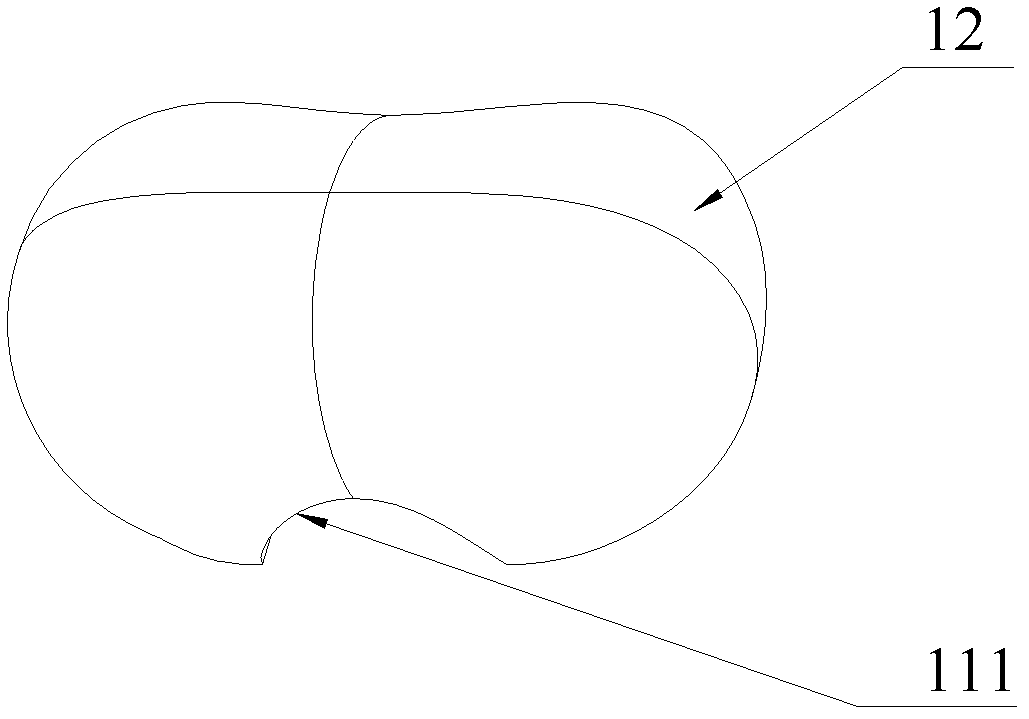
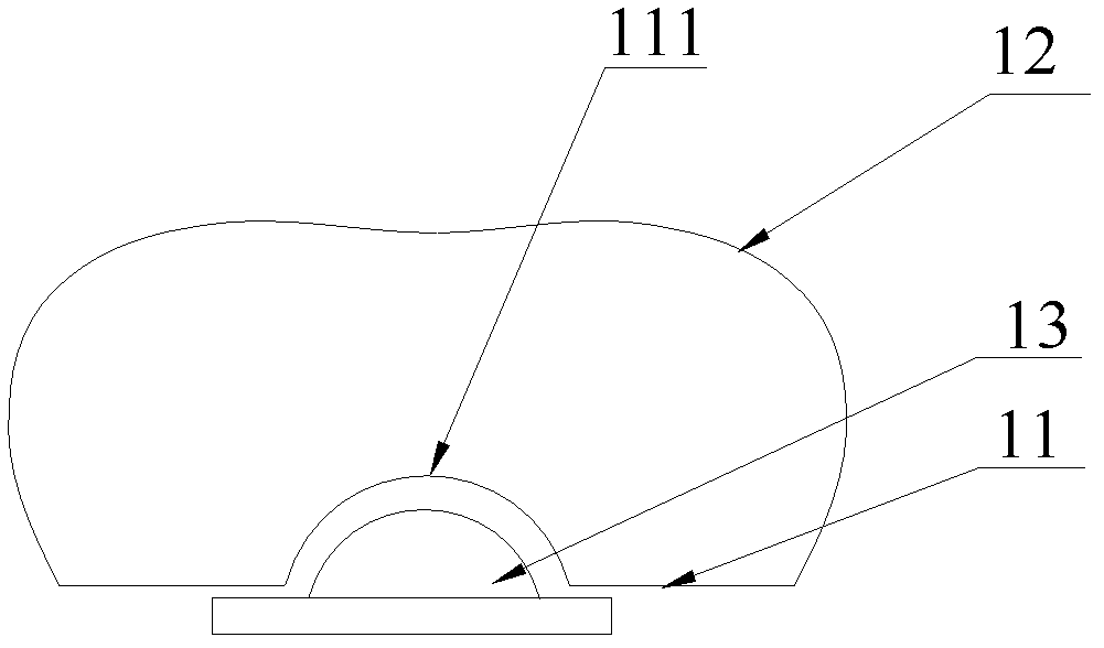
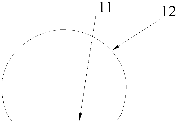
[0022] Reference attached Figure 1~5 , this embodiment provides a light distribution lens, the lens is mainly installed on the outgoing light path of the LED light source to form an independent LED illuminant, and the output direction of the light is adjusted through the lens to form a rectangular spot on the illuminated surface. The lens has a bottom surface 11 and an exit surface 12 . Wherein, the bottom surface 11 is provided with a concave cavity 111 for accommodating the light source 13; the exit surface 12 is a pillow-shaped free-form surface with both ends protruding outward, and the light...


PUM


Abstract

The invention is applied to the field of illumination, and provides a light distribution lens and an LED (Light Emitting Diode) streetlamp. The lens comprises a bottom surface and an outgoing surface. The bottom surface is provided with a cavity for accommodating a light source. The outgoing surface is a bolster-shaped free-form surface with both ends protruding. The light distribution angle of the lens in the length direction is 120-140 degrees, and the light distribution angle in the width direction is 50-90 degrees. According to the light distribution lens provided by the invention, the illuminating length is effectively increased, and illumination outside a region to be illuminated is weakened, so that energy-saving and environment-friendly green illumination is realized. The illuminating requirements of the streetlamp can be better met by a lamp with the lens, in particular to the illuminating requirements for camera and monitoring of an airport enclosure. The light distribution lens and the LED streetlamp can be widely applied to the field of airport illumination.

Description

technical field [0001] The invention belongs to the field of lighting, in particular to a light distribution lens and an LED road lamp. Background technique [0002] In order to meet the lighting requirements of the peripheral boundary camera monitoring of civil airports, the floodlights used need to have a wide range of illumination in the direction of the extension of the outer fence, a large angle, and good lighting effects, but a wide range of lighting is not required in the vertical direction, otherwise it will waste electric power. It also causes light pollution to the surrounding environment. Nowadays, traditional floodlights are mostly used on the periphery of the airport, and the light source uses high-power white LEDs. The luminosity distribution of this light source is Lambert distribution, and the light spot is circular. The light on the road is a circular light spot, about half of the light spot will be scattered outside the road and wasted, resulting in energy...

Claims


Application Information

Patent Timeline
Patent Type & Authority Patents(China)
IPC IPC(8): F21V5/04F21S8/00F21W131/103F21Y101/02
CPCF21Y2101/02F21W2131/103F21V5/04F21Y2115/10
Inventor 周明杰黄俊晖
Owner OCEANS KING LIGHTING SCI&TECH CO LTD
Why Eureka
Try Eureka