Synchronous camera lighting system

A lighting system and synchronous camera technology, which is applied to the components of the TV system, photography, image communication, etc., can solve the problems of not having the camera function, not being able to ensure the same area of ​​camera and lighting, and not being able to perform good real-time camera, etc.

Inactive Publication Date: 2004-05-05
SHANGHAI INST OF OPTICS & FINE MECHANICS CHINESE ACAD OF SCI
View PDF1 Cites 4 Cited by
  • Summary
  • Abstract
  • Description
  • Claims
  • Application Information

AI Technical Summary

Problems solved by technology

Most of the existing lighting systems are single lighting systems without camera function (see utility model patent, a medical lighting appliance, application number: 92204340.X); in actual medical operations, experiments, coal mines and tunnels , when realizing illumination and synchronous camera, often utilize separate camera device (such as video camera etc.) to shoot on the spot, the method cost of this realization synchronous camera lighting is high, and can't carry out very good real-time camera; CCD) camera is fixed on the bracket of the lighting device, but it cannot meet the coaxiality of the lighting beam and the camera collection beam required by the synchronous camera lighting system, so it cannot be guaranteed that the camera and the lighting are in the same area

Method used


Image

  • Synchronous camera lighting system
  • Synchronous camera lighting system
  • Synchronous camera lighting system

Examples


Embodiment Construction

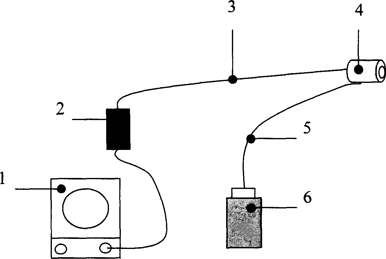
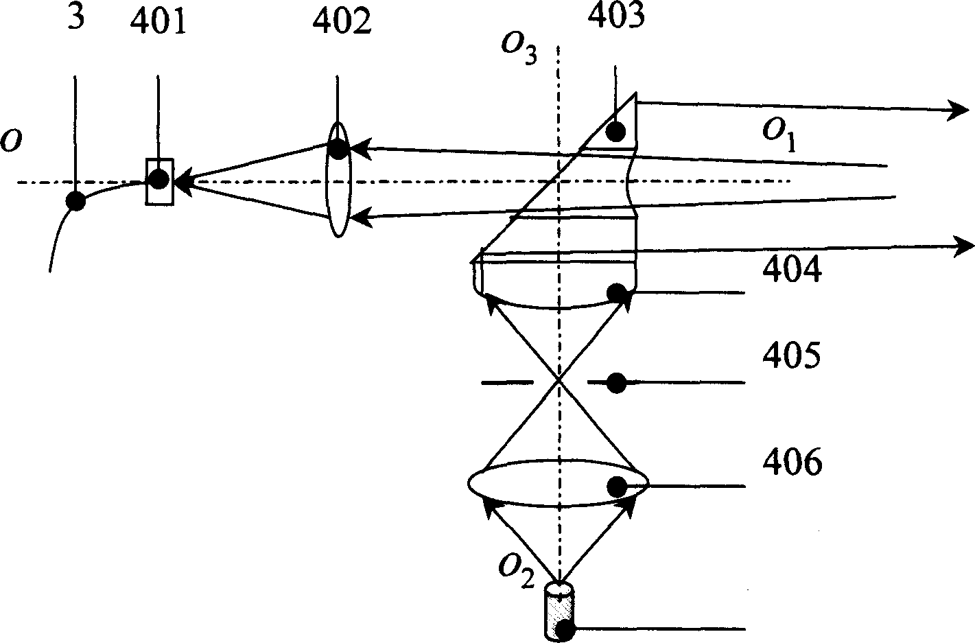
[0015] The synchronous photographing and lighting system of the present invention comprises light source, photographing and illuminating head and signal processing display three parts, as figure 1 , figure 2 , image 3 shown.

[0016] Light source part: including a white light source 6 and an optical fiber bundle 5 connected to the light output end of the white light source 6 for light export, defining the symmetry axis of the outgoing light of the optical fiber bundle 5 as the illumination optical axis o 2 o 3 .

[0017] Camera and illumination head 4: comprise the converging lens 406 that is placed on the advancing direction of the illumination light emitted by the fiber bundle 5, the symmetry axis of the converging lens 406 and the illumination optical axis o 2 o 3 Converging lens 406 converges the illuminating light beam that fiber optic bundle 5 sends out; Comprising diaphragm 405 placed on the illuminating light exit side of converging lens 406, the symmetry axis o...


PUM


Abstract

A synchronous lighting system for camera is composed of light source, lighting unit of camera and information processing unit. It features that a perforated cylindrical reflector is used to realize that the optical axises of lighting and camera are coaxial and the optical sensing surface of CCD is used to convert the optical signals to electric ones for further processing easily. Its advantages are simple structure, light weight and high synchronism of lighting and camera.

Description

Technical field: [0001] The invention is a synchronous photographing and lighting system. It is mainly used in real-time head-mounted camera lighting for medical operations, experiments, coal mines and tunnels. Background technique: [0002] Most of the existing lighting systems for operations, experiments, coal mines and tunnels are single lighting systems, but in some cases, it is often desired to be able to take pictures while lighting. In medicine, in order to better collect important medical data, record the patient's symptoms or the doctor's operation process in real time, to facilitate medical identification, etc., it is often necessary to take a camera while medical lighting is used. In the work of coal mines and tunnels, taking pictures while lighting is also beneficial to the collection of data and the identification of work accidents. Synchronous camera lighting systems often have the following requirements: 1) The lighting beam is coaxial with the camera collec...

Claims


Application Information

Patent Timeline
Patent Type & Authority Applications(China)
IPC IPC(8): G02B6/00G03B15/02H04N5/225
Inventor 徐文东高秀敏干福熹王阳周飞张锋魏劲松
Owner SHANGHAI INST OF OPTICS & FINE MECHANICS CHINESE ACAD OF SCI
Why Eureka
Try Eureka