
Terminal and charging current regulating method

A technology of charging current and adjustment method, which is applied in secondary battery charging/discharging, battery circuit devices, current collectors, etc., and can solve problems affecting user experience and heating of the whole terminal

Active Publication Date: 2015-04-08
DONGGUAN YULONG COMM TECH +1
View PDF5 Cites 0 Cited by
  • Summary
  • Abstract
  • Description
  • Claims
  • Application Information

AI Technical Summary

Problems solved by technology

The disadvantage of the high-current charging solution is that it will cause the terminal to heat up seriously. If the user is operating the terminal at this time, it will seriously affect the user experience.

Method used


Image

  • Terminal and charging current regulating method
  • Terminal and charging current regulating method
  • Terminal and charging current regulating method

Examples


Embodiment Construction

[0029] In order to be able to understand the above objectives, features and advantages of the present invention more clearly, the present invention will be further described in detail below in conjunction with the accompanying drawings and specific embodiments.

[0030] In the following description, many specific details are set forth in order to fully understand the present invention. However, the present invention can also be implemented in other ways different from those described here. Therefore, the protection scope of the present invention is not subject to the specific implementations disclosed below. Limitations of cases.

[0031] The present invention will be further described below in conjunction with the drawings and embodiments. It should be noted that the embodiments of the application and the features in the embodiments can be combined with each other if there is no conflict.

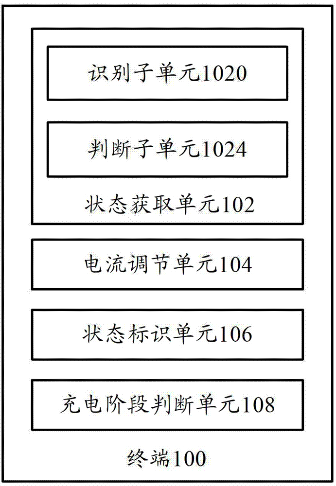
[0032] figure 1 A block diagram of a terminal according to an embodiment of the present inve...


PUM


Abstract

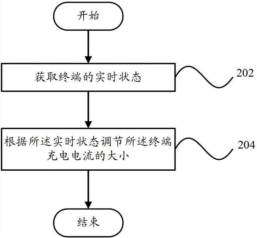
The invention provides a terminal which comprises a state acquisition unit and a current regulating unit, wherein the state acquisition unit is used for acquiring a real-time state of the terminal; and the current regulating unit is used for regulating the size of a charging current of the terminal according to the real-time state. The invention also provides a charging current regulating method. By the technical scheme adopted by the invention, the size of the charging current can be automatically regulated according to the state of the terminal, so that the influence of the heating of the terminal on user experience is reduced.

Description

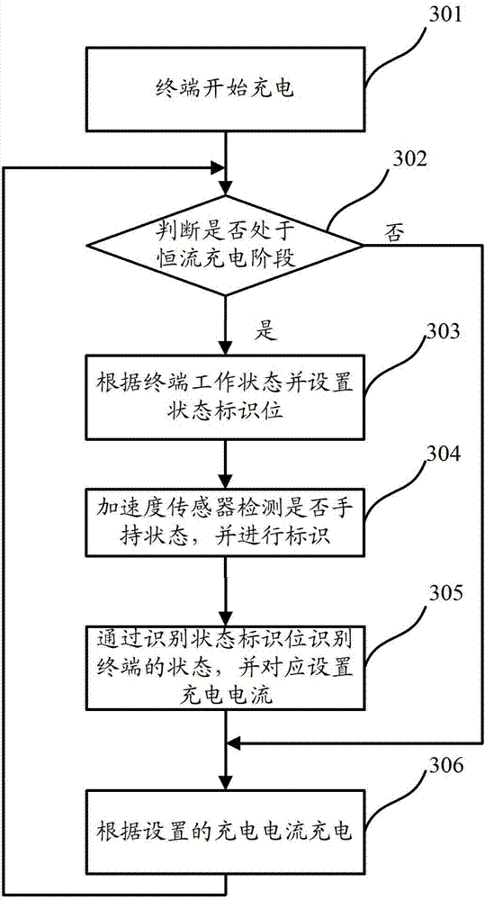
Technical field [0001] The present invention relates to the technical field of terminal power management, in particular to a terminal and a charging current adjustment method. Background technique [0002] The charging of mobile phones and other terminals is divided into three stages: trickle, constant current, and constant voltage, and the constant current stage occupies a long time in the entire charging process. In existing solutions, the maximum current drawn by the terminal from the charger in the constant current phase is often set to a fixed value. As the battery capacity of smart terminals increases, the problem with too small charging current is that the charging time is too long. Therefore, for terminals with large-capacity batteries, the prior art usually uses large currents to charge the terminals. The disadvantage of the high-current charging scheme is that it will cause the terminal to heat up seriously. If the user is holding the terminal for operation at this tim...

Claims


Application Information

Patent Timeline
Patent Type & Authority Patents(China)
IPC IPC(8): H01M10/44H02J7/04
CPCY02E60/10
Inventor 杜立剑张志立
Owner DONGGUAN YULONG COMM TECH
Learn More