Antenna calibrating method and antenna s calibrating device in time division duplex coordinated multiple point system

An antenna calibration and time-division duplexing technology, applied in diversity/multi-antenna systems, transmission systems, space transmit diversity, etc., can solve the problems of destroying the uplink and downlink reciprocity of the cell, and realize difficulties, so as to improve the performance of channel reciprocity , easy to promote and achieve simple effects

Active Publication Date: 2012-12-26
ZTE CORP
View PDF4 Cites 25 Cited by
  • Summary
  • Abstract
  • Description
  • Claims
  • Application Information

AI Technical Summary

Problems solved by technology

In the existing antenna calibration schemes proposed for the CoMP system, either the intra-cell calibration is performed first and then the inter-cell calibration, or the intra-cell and inte

Method used


Image

  • Antenna calibrating method and antenna s calibrating device in time division duplex coordinated multiple point system
  • Antenna calibrating method and antenna s calibrating device in time division duplex coordinated multiple point system
  • Antenna calibrating method and antenna s calibrating device in time division duplex coordinated multiple point system

Examples


Embodiment 1

[0168] The antenna calibration method in this embodiment is specifically described as follows:

[0169] Step 101: The reference antenna n1 of eNB1 and the reference antenna w1 of eNB2 send pilot signals to the antenna m1 of the CoMP user through the air interface, and the user estimates the channel from the reference antenna n1 of eNB1 to the user reference antenna m1 after receiving the pilot signal information and channel information from the reference antenna w1 of eNB2 to the user reference antenna m1, and feed it back to eNB1.

[0170] Step 102: The antenna m1 of the CoMP user sends a pilot signal to eNB1 and eNB2, and eNB1 and eNB2 only use antenna n1 and antenna w1 to receive the pilot signal, and eNB1 estimates the channel information from user antenna m1 to eNB1 after receiving the pilot signal , eNB2 estimates channel information from user antenna m1 to eNB2 after receiving the pilot signal.

[0171] Step 103: eNB1 obtains correction coefficients on antenna n1 of eN...

Embodiment 2

[0176] The antenna calibration method in this embodiment is specifically described as follows:

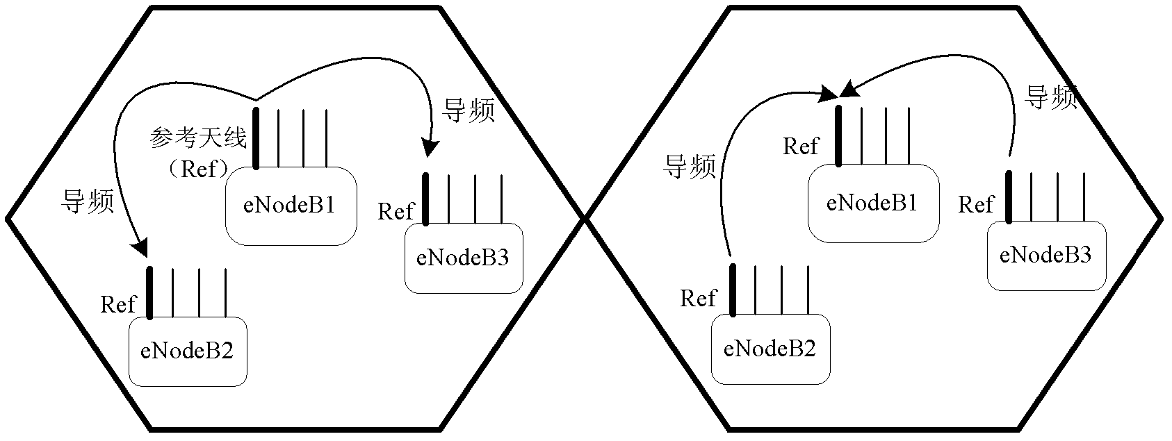
[0177] Step 201: The reference antenna n1 of eNB1 sends a pilot signal to the reference antenna w1 of eNB2 through the air interface. After receiving the pilot signal, eNB2 estimates the channel information from antenna n1 of eNB1 to antenna w1 of eNB2, and feeds it back to eNB1.

[0178] Step 202: The reference antenna w1 of eNB2 sends a pilot signal to the reference antenna n1 of eNB1 through the air interface. After receiving the pilot signal, eNB1 estimates the channel information between the antenna w1 of eNB2 and the antenna n1 of eNB1.

[0179] Step 203: eNB1 obtains correction coefficients on antenna n1 of eNB1 and antenna w1 of eNB2 based on the obtained round-trip channel information between eNB1 and eNB2.

[0180] Step 204: eNB1 notifies eNB2 of the correction coefficient on antenna w1 of eNB2.

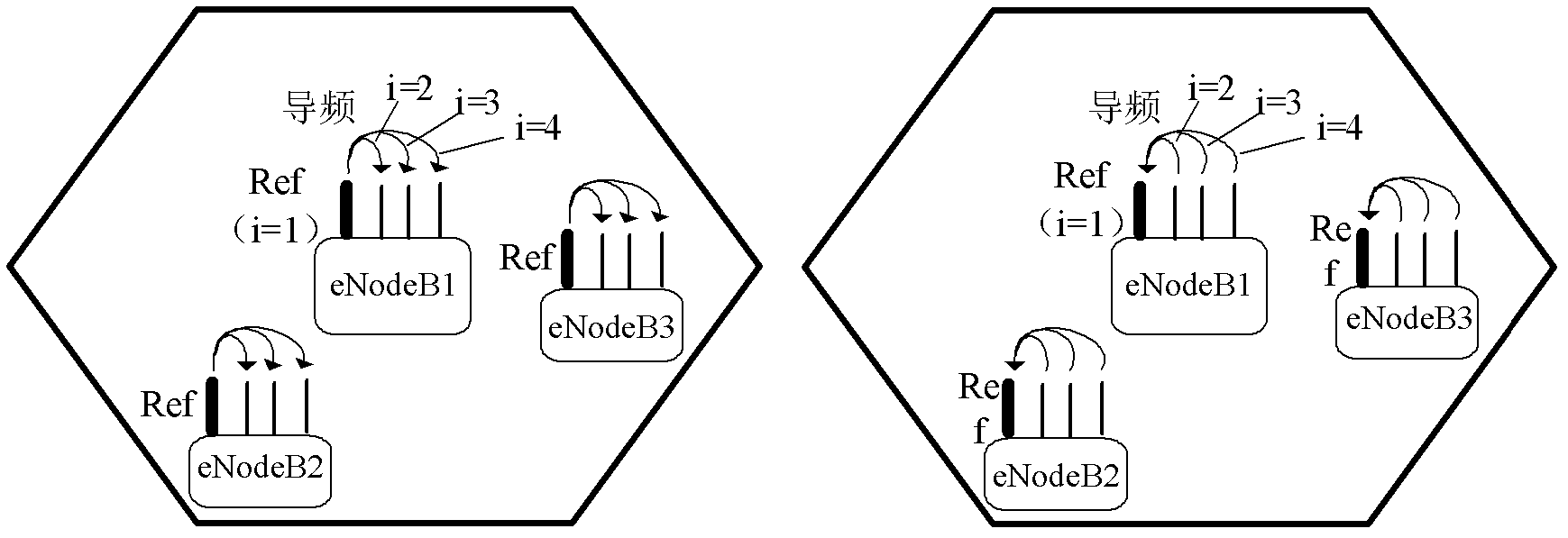
[0181] Step 205: eNB1 calibrates other antennas on eNB1 based on antenna ...

Embodiment 3

[0184] The antenna calibration method in this embodiment is specifically described as follows:

[0185] Step 301: The reference antenna n1 of eNB1 sends a pilot signal to the reference antenna w1 of eNB2 through a feeder or a dedicated correction circuit. After receiving the pilot signal, eNB2 estimates the channel information from antenna n1 of eNB1 to antenna w1 of eNB2, And feed it back to eNB1.

[0186] Step 302: The reference antenna w1 of eNB2 sends a pilot signal to the reference antenna n1 of eNB1 through a feeder or a dedicated correction circuit. After receiving the pilot signal, eNB1 estimates the channel between antenna w1 of eNB2 and antenna n1 of eNB1 information.

[0187] Step 303: eNB1 obtains correction coefficients on antenna n1 of eNB1 and antenna w1 of eNB2 based on the obtained round-trip channel information between eNB1 and eNB2.

[0188] Step 304: eNB1 notifies eNB2 of the correction coefficient on antenna w1 of eNB2.

[0189] Step 305: eNB1 calibrate...


PUM


Abstract

The invention discloses an antenna calibrating method and an antenna calibrating device used in a time division duplex coordinated multiple point system. The antenna calibrating method comprises a step of calibrating antennas among cells by a network side: selecting a standard antenna, taking the standard antenna as the standard, and calibrating reference antennas in all the cells; and a step of calibrating the antennas in the cells by the network side again: taking the reference antenna of the cell as the standard in each cell, and calibrating other antennas in the cell, excepting the reference antenna, wherein one of the antennas of the cell is selected as the reference antenna of the cell in each cell respectively. By using the protocol of calibrating the antennas among the cells firstly and then calibrating antennas in the cell on the basis of calibration among the cells, the reciprocity of an uplink and a downlink in the calibrated cell cannot be damaged; the channel reciprocity performance of the time division duplex (TDD) coordinated multiple point (CoMP) system is improved, so that the transmission performance of the CoMP system is also improved.

Description

technical field [0001] The invention relates to the technical field of wireless communication, in particular to an antenna calibration method and device in a time-division duplex coordinated multi-point system. Background technique [0002] The Long Term Evolution (LTE for short) system simultaneously defines two different duplex modes: Frequency Division Duplexing (FDD for short) and Time Division Duplexing (TDD for short). FDD receives and transmits on two separate symmetrical frequency channels, and uses a guard frequency band to separate the receive and transmit channels. TDD uses time to separate receiving and sending channels, and its receiving and sending use different time slots of the same frequency carrier as the bearer of the channel. [0003] The main difference between TDD and FDD is that the uplink and downlink physical channels of TDD have symmetry (or called reciprocity), while FDD does not have such reciprocity. Due to reciprocity, the base station (eNodeB...

Claims


Application Information

Patent Timeline
IPC IPC(8): H04B7/04H04B17/00H04B17/12H04B17/21
Inventor 弓宇宏孙云锋陈艺戬张峻峰陈东丽
Owner ZTE CORP
Why Eureka
Try Eureka