Cable provided with reinforcing board and reinforcing board

A technology for strengthening boards and cables, applied in the direction of flat/ribbon cables, insulated cables, cables, etc., to achieve the effect of ensuring firm connection and easy miniaturization

Inactive Publication Date: 2015-04-08
YAMAICHI ELECTRONICS
View PDF5 Cites 0 Cited by
  • Summary
  • Abstract
  • Description
  • Claims
  • Application Information

AI Technical Summary

Problems solved by technology

In addition, in order to achieve further miniaturization or weight reduction of such electronic equipment, it is a large technical problem to reduce the volume occupied by conventional connectors and flat cables on the surface of the main substrate.

Method used


Image

  • Cable provided with reinforcing board and reinforcing board
  • Cable provided with reinforcing board and reinforcing board
  • Cable provided with reinforcing board and reinforcing board

Examples


no. 1 approach

[0025] refer to Figure 1 to Figure 6 , the cable with a reinforcing plate and the reinforcing plate according to the first embodiment of the present invention will be described.

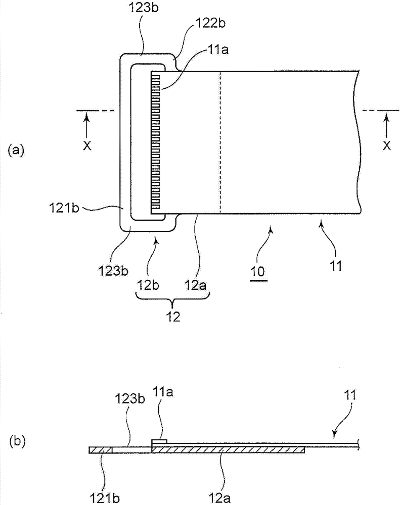
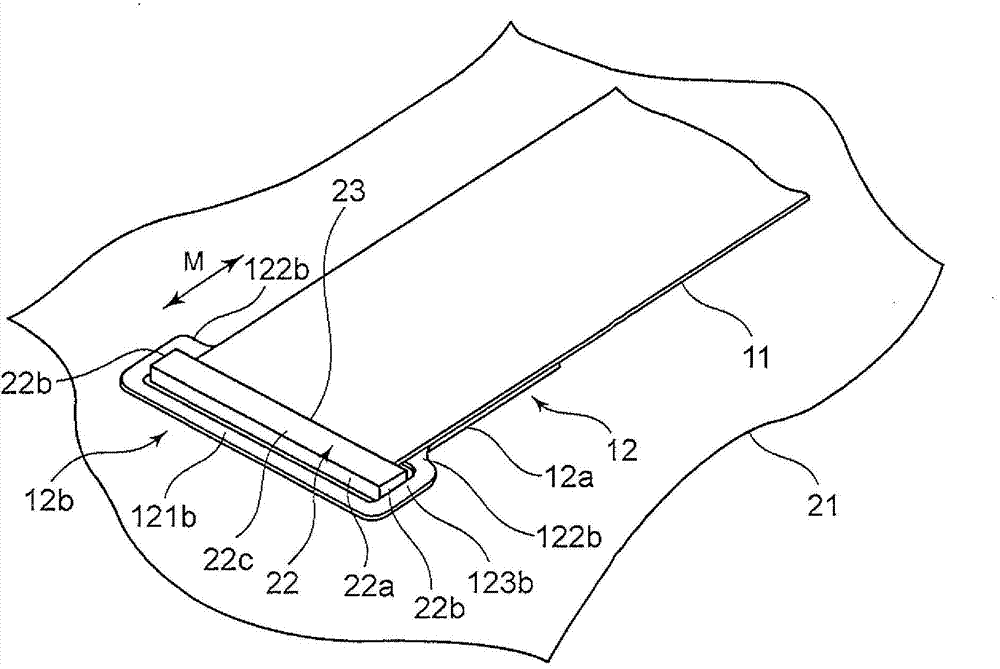
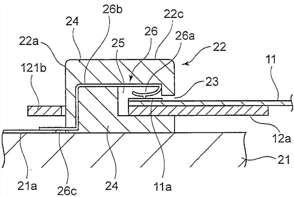
[0026] Such as figure 1 As shown, the cable 10 with a reinforcing plate according to this embodiment has a flat cable 11 made of, for example, FFC, and a reinforcing plate 12 fixedly attached to the front end region of the flat cable 11 . Here, the reinforcement plate 12 includes: a support plate 12a supporting one of the front and rear surfaces of the flat cable 11; and an elastically deformable engaging arm 12b connected to the support plate 12a. In addition, on the other surface of the front end portion of the flat cable 11, for example, a connection terminal 11a is formed.

[0027] The engagement arm 12b has an arm front end portion 121b engaged with a front end portion of the connector as described later, and an arm base end portion 122b protruding left and right from both side ends of the su...

no. 2 approach

[0054] Next, refer to Figure 7A cable with a reinforcing plate according to a second embodiment will be described. In the second embodiment, the shape of the engaging arm of the reinforcing plate is different from the annular shape in the first embodiment.

[0055] Such as Figure 7 As shown, in the cable with a reinforcing plate of this embodiment, the reinforcing plate 42 is fixedly attached to the front end region of the flat cable 11 as described in the first embodiment. Here, the reinforcement plate 42 includes: a support plate 42a supporting one of the front and rear surfaces of the flat cable 11; and an elastically deformable engaging arm 42b connected to the support plate 42a.

[0056] Also, the engaging arm 42b has a first arm piece 421b and a second arm piece 422b so as to engage with the connector front end portion 22a and the connector side end portion 22b of the connector 22 surface-mounted on the main board 21 . Here, the first arm piece 421b and the second a...

no. 3 approach

[0060] Next, refer to Figure 8 A cable with a reinforcing plate according to a third embodiment will be described. In the third embodiment, unlike the first embodiment, the engaging arm of the reinforcing plate is formed in a structure that partially covers and contacts the upper end of the connector.

[0061] Such as Figure 8 As shown, in the cable with a reinforcing plate of this embodiment, the reinforcing plate 52 is fixedly attached to the front end region of the flat cable 11 as described in the first embodiment. The reinforcement plate 52 includes: a support plate 52a supporting one of the front and rear surfaces of the flat cable 11; and an elastically deformable engaging arm 52b connected to the support plate 52a.

[0062] The engaging arm 52b has an arm front end portion 521b engageable with the connector front end portion 22a of the connector 22, and an arm base end portion 522b protruding left and right from both side ends of the support plate 52a. Furthermore...


PUM

PropertyMeasurementUnit
thicknessaaaaaaaaaa
thicknessaaaaaaaaaa
thicknessaaaaaaaaaa

Abstract

The invention provides a cable provided with a reinforcing board. The cable provided with the reinforcing board can guarantee the solid connection and easy disassembly of the flat cable relatively to a connection and is small in size. The cable (10) provided with the reinforcing board is provided with the flat cable (11) and the reinforcing board (12) installed on the front end area of the flat cable (11) fixedly. The reinforcing board (12) includes a support board (12a) supporting one of the surface and the back face of the flat cable (11); and a clamping arm (12b) connected with the support board (12a) and capable of elastic transformation. A connection terminal (11a) is formed on the other face of the front end part of the flat cable (11). The clamping arm (12b) is provided with an arm front end part (121b), an arm base end part (122b) and an arm side part (123b). The clamping arm (12b) is clamped with the outer periphery of the connector, thereby avoiding the poor connection caused by separation, shift or inclined insertion caused by the stretching of the flat cable (11).

Description

technical field [0001] The present invention relates to a flat cable connected with a connector, and in particular, to a cable with a reinforcing plate and a reinforcing plate thereof capable of easily realizing miniaturization of the connector and firm connection of the connector and the flat cable. Background technique [0002] In the electrical connection between the electrical components inside the electronic equipment, on the main substrate such as printed circuit board (PCB: printed circuit board), the flexible cable connector (hereinafter referred to as the connector) is connected to the flexible circuit board. Flat cables such as flat cables (FFC: flexible flat cable) and flexible printed circuit boards (FPC: flexible printed circuit). The connector is connected to the circuit wiring of the main board, and is mounted on the main board by, for example, surface mounting. Next, the flat cable is connected to the connector by, for example, fitting. In order to prevent ...

Claims


Application Information

Patent Timeline
Patent Type & Authority Patents(China)
IPC IPC(8): H01B7/18H01B7/08H01R13/46H01R12/59
Inventor 山﨑景米沢章
Owner YAMAICHI ELECTRONICS
Why Eureka
Try Eureka