
Angle adjusting device for display screen

An angle adjustment device and technology of a display screen, applied in the field of display screen, can solve the problems of limited range of angle adjustment, inability to achieve the placement angle, processing error of the box, etc., to achieve the effect of overcoming uneven splicing

Active Publication Date: 2013-01-02
SHENZHEN INFILED ELECTRONICS
View PDF4 Cites 6 Cited by
  • Summary
  • Abstract
  • Description
  • Claims
  • Application Information

AI Technical Summary

Problems solved by technology

[0004] The traditional assembled display screen usually fixes two adjacent display cabinets, and the two cabinets are installed together by fixed connection, so that the two display screens are in the same plane. However, sometimes, combined The display screen is curved, so it is necessary to customize the corresponding display box according to the size of the arc. When installing, fix the customized display box together. This structure can only be placed in a single Poor sex
[0005] The patent document with the publication number CN201957366 proposed by the applicant on February 25, 2011 discloses an angle adjustment device for LED display screens. The adjustment device is installed between two display screen boxes and can be adjusted according to needs. The angle between two adjacent display cabinets can be adjusted to different angles according to different usage requirements. Although this structure can adjust different angles to meet different usage requirements, but , because the angle adjustment is achieved through the cooperation of pins and pin holes, and there is a certain distance between two adjacent pin holes, therefore, the range of angle adjustment is relatively limited, and, due to the error of box processing , when the display screen is placed, usually due to the processing error of the box body, the required placement angle cannot be achieved

Method used


Image

  • Angle adjusting device for display screen
  • Angle adjusting device for display screen
  • Angle adjusting device for display screen

Examples


Embodiment Construction

[0028] Below, in conjunction with accompanying drawing and specific embodiment, the present invention is described further:

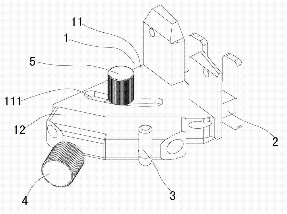
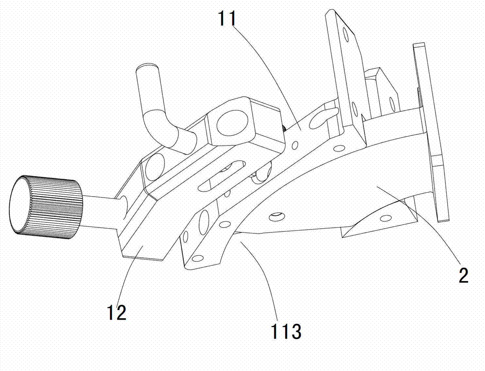
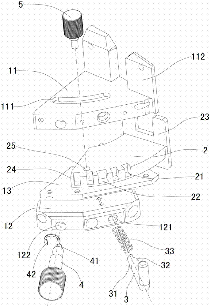
[0029] Such as figure 1 , figure 2 as well as image 3 As shown, it is an angle adjustment device for a display screen of the present invention, which includes a fixed seat 1 and a movable plate 2, the fixed seat 1 includes a fixed block 11, a pin seat 12 and a cover plate 13, and the lower surface of the fixed block 11 is formed by Its right side is inwardly provided with an arc chute 113 (figure not shown), and the cover plate 13 is detachably connected to the lower surface of the fixed block 11, and the cover plate 13 is sealed on the outside of the arc chute 113, so that the arc Shaped chute 113 only has an opening on the right side of fixed block 11, and movable plate 2 is the arc-shaped plate shape that matches with arc-shaped chute 113, and its movably inserts in arc-shaped chute 113, because movable plate 2 Keeping consistent with the radian...


PUM


Abstract

An angle adjusting device for a display screen comprises a fixed seat and a movable plate. An arc sliding groove is arranged on the fixed seat, a screw hole and a pin hole which are communicated with the inside of the arc sliding groove are arranged on the lateral face of the fixed seat. The movable plate is an arc plate matched with the arc sliding groove and is movably inserted in the arc sliding groove, a plurality of grooves are arranged on one lateral edge of the movable plate corresponding to the pin hole, and the inner side end portion of the movable plate inserted in the arc sliding groove forms a pressure bearing end. A micro adjusting pin is connected in the screw hole in screw mode, and the end portion of the micro adjusting pin is in the shape of a cone with small outside and large inside and matched with the pressure bearing end. A lock pin is connected in the pin hole in penetrating mode, a spring is sleeved on the outside of the lock pin, the spring is embedded in the pin hole to be located between a stop structure at the inner side end of the lock pin and the outer side end of the pin hole, and an arc face is arranged at the front end of the lock pin. The angle adjusting device utilizes the micro adjusting device and effectively overcomes the shortcoming of irregular splicing caused by box processing errors.

Description

[0001] technical field [0002] The invention relates to the technical field of display screens, in particular to an angle adjustment device for a display screen. [0003] Background technique [0004] The traditional assembled display screen usually fixes two adjacent display cabinets, and the two cabinets are installed together by fixed connection, so that the two display screens are in the same plane. However, sometimes, combined The display screen is curved, so it is necessary to customize the corresponding display box according to the size of the arc. When installing, fix the customized display box together. This structure can only be placed in a single Sex is poor. [0005] The patent document with the publication number CN201957366 proposed by the applicant on February 25, 2011 discloses an angle adjustment device for LED display screens. The adjustment device is installed between two display screen boxes and can be adjusted according to needs. The angle between tw...

Claims


Application Information

Patent Timeline
Patent Type & Authority Applications(China)
IPC IPC(8): H05K5/02
Inventor 胡日浩李亚斌杨立山
Owner SHENZHEN INFILED ELECTRONICS
Learn More