Fan-and-filter unit

A filter and fan technology, applied in the field of fan cover, can solve the problem of complex filter pad monitoring unit, etc., and achieve the effect of low energy consumption

Active Publication Date: 2013-01-02
RITTALWERK RUDOLF LOH GMBH & CO KG
View PDF8 Cites 6 Cited by
  • Summary
  • Abstract
  • Description
  • Claims
  • Application Information

AI Technical Summary

Problems solved by technology

This type of filter pad monitoring unit is relatively complex and is primarily intended for service personnel

Method used


Image

  • Fan-and-filter unit
  • Fan-and-filter unit
  • Fan-and-filter unit

Examples


Embodiment Construction

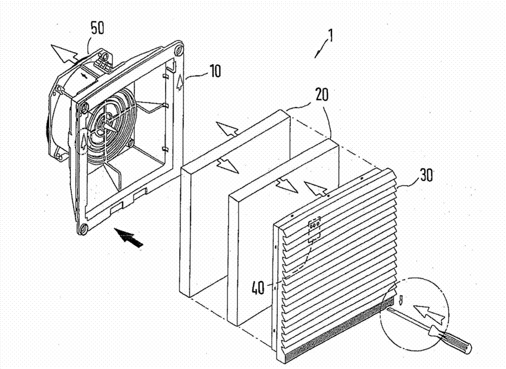
[0028] figure 1 The fan and filter unit 1 is shown in a perspective view, comprising a fan housing 10 with a fan unit 50, a filter pad arrangement 20 and a fan cover 30, and also comprising a filter pad monitoring unit 40, with a fan motor 51 mounted on the fan unit 50 (see also figure 2 ).

[0029] The fan housing 10 has, on its front side facing the fan guard 30 , a large, for example rectangular or square opening, which is respectively surrounded by a continuous rectangular or square frame and tapers towards the rear, as if with a wall area connected to the frame The funnel of the segment thus has a frusto-conical shape, wherein the parallel rear side facing away from the front side is closed by a wall segment. A circular hole is provided on the rear side wall section of the filter housing 10, surrounded by a rearwardly protruding cylindrical section, and accommodates a fan motor and a fan wheel driven by the fan motor. The fan unit 50 has a protective grille on its fro...


PUM


Abstract

The invention relates to a fan-and-filter unit to be mounted in the wall of a switch cabinet or housing, comprising a fan unit (50) inserted in a fan housing (10), a filter mat arrangement (20) mounted upstream of the fan unit and a fan cover (30) immobilizing the filter mat. According to an advantageous embodiment of the fan-and-filter unit, the fan-and-filter unit has a filter mat monitoring unit (40) which is designed to detect the service life and / or a degree of soiling of the filter mat arrangement (20) and which comprises an insert (41) integrated into the fan housing or the fan cover (30) and having an illuminated display (45) visible from the exterior of the fan cover (30) facing away from the fan unit (50). Said display is designed to display information at least when a service life that is predetermined or can be predetermined and / or a degree of soiling that is predetermined or can be predetermined is exceeded.

Description

technical field [0001] The invention relates to a fan and filter unit mounted on the wall of a switchgear or switch housing, comprising a fan unit inserted into the fan housing, a filter pad arrangement mounted upstream of the fan unit, and a fan cover securing the filter pad. Background technique [0002] DE 19860433 B4 describes a fan and filter unit of this type installed in an opening in the wall of a switch cabinet or switch housing. The fan and filter unit comprises a fan housing in which is arranged a fan unit with a motor and a fan wheel for drawing air from the outside into or exhausting air from the inside of the switchgear , and, the fan case is covered toward the outside by a milk-shaped vent grille having horizontal sheets and an air outlet between the horizontal sheets. The filter mat is inserted between the fan case and the fan unit, thereby being held at the fan case by the support grille. Depending on the field in which the switchgear or switch housing is ...

Claims


Application Information

Patent Timeline
Patent Type & Authority Applications(China)
IPC IPC(8): H05K7/20B01D46/00
CPCB01D46/10F24F2011/0093B01D46/0086H05K7/20181B01D2273/30B01D46/44B01D46/4254F24F11/39
Inventor R.哈特曼B.莱纳特S.施奈德
Owner RITTALWERK RUDOLF LOH GMBH & CO KG
Why Eureka
Try Eureka