Combined battery cell bracket structure

A bracket structure, combined technology, applied in the direction of structural parts, circuits, electrical components, etc., can solve the problem of increased cost, and achieve the effect of reducing the overall weight, keeping the height consistent, and quickly connecting in series and parallel.

Pending Publication Date: 2018-08-31
安徽统凌科技新能源有限公司
View PDF0 Cites 5 Cited by
  • Summary
  • Abstract
  • Description
  • Claims
  • Application Information

AI Technical Summary

Problems solved by technology

[0002] Reducing energy consumption, energy saving and environmental protection are the themes of social development today. Under this background, lithium batteries are gradually becoming mature in technology. At present, the use of lithium battery packs is to use a battery frame to combine multiple batteries to form a set. Batteries, however, the traditional cell holder can only supply a fixed number of batteries. If you want to change the number of batteries, you will be limited by the predetermined number of battery cell perforations, and you need to remake a new battery holder, which will cost more , so we propose a combined cell support structure to solve the above problems

Method used


Image

  • Combined battery cell bracket structure
  • Combined battery cell bracket structure
  • Combined battery cell bracket structure

Examples


Embodiment Construction

[0018] The following will clearly and completely describe the technical solutions in the embodiments of the present invention with reference to the accompanying drawings in the embodiments of the present invention. Obviously, the described embodiments are only some, not all, embodiments of the present invention. Based on the embodiments of the present invention, all other embodiments obtained by persons of ordinary skill in the art without making creative efforts belong to the protection scope of the present invention.

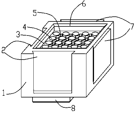
[0019] see Figure 1-5 , the present invention provides a technical solution: a combined cell support structure, including a casing 1 and a cell frame 3, the cell frame 3 is fixedly installed in the casing 1, and a cell hole 4 is opened on the cell frame 3, There are weight-reducing holes 5 on the battery frame 3 between the battery holes 4, the first card slots 2 are opened on two adjacent sides of the housing 1, and the first clamping blocks 7 are fixedly in...


PUM


Abstract

The invention discloses a combined battery cell bracket structure. The combined battery cell bracket structure comprises a casing and a battery cell bracket, wherein the battery cell bracket is arranged in the casing and provided with battery cell holes; the battery cell bracket among the battery cell holes is provided with lightening holes; first clamping grooves are formed in two adjacent side faces of the casing; first clamping blocks are arranged on another two adjacent side faces of the casing; a connecting block is arranged on the bottom surface of the casing; a connecting groove is formed in the top of an inner cavity of the casing; end covers are arranged on the top surface and the bottom surface of the casing; a connecting piece is arranged between the end cover on the top surfaceand the end cover on the bottom surface of the casing. A battery cell is put into each battery cell hole; according to the size of a battery pack, the first clamping block of one battery cell bracketis clamped in the corresponding first clamping groove of the other battery cell bracket, and the connecting block of one layer of battery pack is inserted into the connecting groove of the other layer of battery pack; the end covers are respectively arranged on the upper end face and the lower end face of the battery pack, and second clamping blocks are clamped into second clamping grooves, so that the whole battery pack is fixed and serial and parallel splicing of the battery cell bracket with any quantity is realized.

Description

technical field [0001] The invention relates to the technical field of batteries, in particular to a combined battery cell support structure. Background technique [0002] Reducing energy consumption, energy saving and environmental protection are the themes of social development today. Under this background, lithium batteries are gradually becoming mature in technology. At present, the use of lithium battery packs is to use a battery frame to combine multiple batteries to form a set. Batteries, however, the traditional cell holder can only supply a fixed number of batteries. If you want to change the number of batteries, you will be limited by the predetermined number of battery cell perforations, and you need to remake a new battery holder, which will cost more , so we propose a combined cell support structure to solve the above problems. Contents of the invention [0003] The purpose of the present invention is to provide a combined cell support structure to solve the ...

Claims


Application Information

Patent Timeline
Patent Type & Authority Applications(China)
IPC IPC(8): H01M2/10H01M50/20
CPCH01M50/20Y02E60/10
Inventor 杨力平廖鹏王洪祥
Owner 安徽统凌科技新能源有限公司
Why Eureka
Try Eureka