Cooling apparatus for hot nozzle of injection mould

A technology of injection mold and cooling device, which is applied in the field of plastic mold manufacturing, can solve the problems of reduced efficiency of the hot runner cooling device, uncontrollable temperature around the hot nozzle, inconvenient installation of the hot nozzle, etc., achieve good cooling effect, improve appearance defects, Good cooling effect

Inactive Publication Date: 2016-08-31
ZHEJIANG SAIHAO IND CO LTD
View PDF3 Cites 6 Cited by
  • Summary
  • Abstract
  • Description
  • Claims
  • Application Information

AI Technical Summary

Problems solved by technology

[0005] Although the above-mentioned hot runner cooling device solves the problem of excessively high temperature of the hot nozzle to a certain extent, it is inconvenient to install the hot nozzle because the cooling jacket is installed on the hot nozzle. The surface of the hot nozzle reduces the temperature of the hot nozzle, making the temperature around the hot nozzle uncontrollable, thus reducing the efficiency of the hot runner cooling device

Method used


Image

  • Cooling apparatus for hot nozzle of injection mould
  • Cooling apparatus for hot nozzle of injection mould

Examples


Embodiment 1

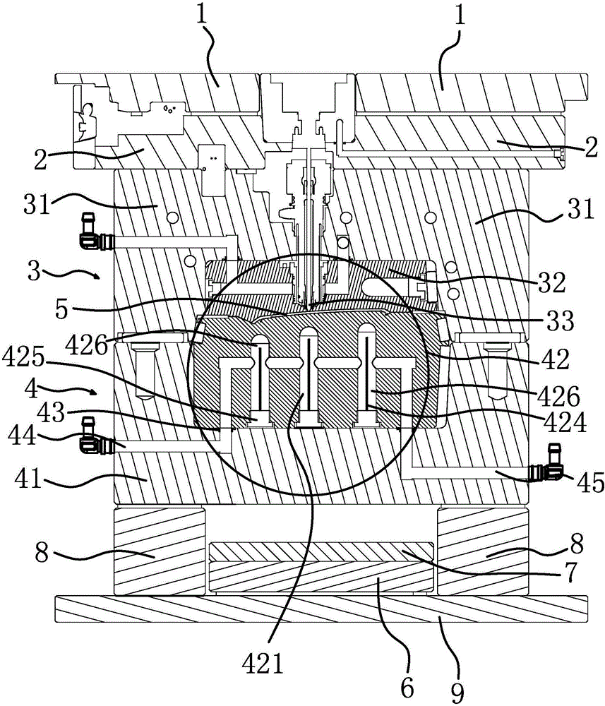
[0039] Such as figure 1 As shown, in the cooling device for the hot nozzle of an injection mold, the injection mold includes a panel 1, a hot runner frame plate 2, a fixed mold 3, a hot nozzle 33 inserted in the fixed mold 3, a movable mold 4, and a bottom needle plate. 6. The needle plate 7, the square iron 8 and the bottom plate 9. The cooling device includes a cooling water well 421, a water inlet passage 44 and a water outlet passage 45 arranged in the movable mold 4.

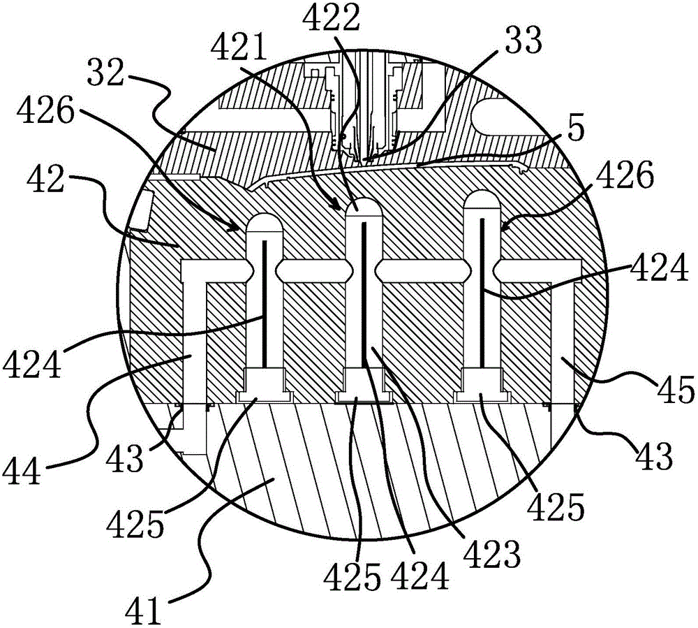
[0040] Specifically, such as figure 1 with figure 2 As shown, the movable mold 4 includes a movable mold plate 41 and a movable mold insert 42. The cooling water well 421 is arranged in the movable mold insert 42, and the water inlet passage 44 and the water outlet passage 45 are both located in the movable mold 4 insert and the movable mold plate 41. , And the driven template 41 is connected to the mold temperature machine when it passes through. The upper part of the cooling water well 421 is a cooling cavi...

Embodiment 2

[0050] The structural features of the cooling device for the injection mold hot nozzle of this embodiment are basically the same as those of the first embodiment. The difference is that the guide is a water-carrying pipe, one end of the water-carrying pipe is provided with a cooling port, and the cooling port is arranged in the cooling cavity In 422, one side of the water conveying pipe is provided with a water conveying port, which is connected to the water inlet channel 44. The water conveying pipe is arranged in the cooling water well 421 and connected to the movable mold 4, and the water conveying port is connected to the water inlet channel 44 through which the cooling water passes The water inlet channel 44 is guided from the water port to the water pipe, and the cooling water reaches the cooling port under the action of water pressure. At this time, the cooling port is opened in the cooling cavity 422, so that the cooling water can fill the cooling cavity 422. , The water...


PUM


Abstract

The invention provides a cooling apparatus for a hot nozzle of an injection mould and belongs to the technical field of plastic mould manufacturing. The invention solves problems of poor cooling effects and uncontrollable temperature in the hot nozzle of an injection mould in the prior art. The injection mould in the invention includes a moving die, a fixed die and the hot nozzle which passes through the fixed die. The cooling apparatus includes a cooling water well, a water inlet flow path and a water outlet flow path which are all arranged in the moving die. The upper part of the cooling water well is a cooling chamber which is arranged below the hot nozzle. The water inlet flow path and the water outlet flow path are both communicated with the cooling water well. A flow guide member is arranged inside the cooling water well and is used for guiding cooling water flowing into the cooling water well from the water inlet flow path to pass through the cooling chamber and then flow into the water outlet flow path. The cooling apparatus can quickly reduce the temperature of the hot nozzle and an injection moulding part.

Description

Technical field [0001] The invention belongs to the technical field of plastic mold manufacturing, and relates to a cooling device for a hot nozzle of an injection mold. Background technique [0002] At present, injection molding has occupied a very important position in the molding of plastic injection molded parts in the Chinese market. Injection molding is mainly divided into cold runners and hot runners. Injection hot nozzles are mainly used on hot runners, while hot runner injection molds have a direct front end. Point to inject the glue on the surface of the injection molded part. After the molten plastic injection is completed, the temperature of the glue feeding device is very high, resulting in the mold temperature in the surrounding area of ​​the hot nozzle being higher than other areas. For the hot nozzle, the temperature is too high, causing the gate part to become locally hot, thus It is easy to cause hot stamping and gate flash at the hot runner sprue. [0003] In re...

Claims


Application Information

Patent Timeline
Patent Type & Authority Applications(China)
IPC IPC(8): B29C45/73
CPCB29C45/7312
Inventor 虞伟炳李金国
Owner ZHEJIANG SAIHAO IND CO LTD
Why Eureka
Try Eureka