Antiknock container sealing structure

A container sealing and sealing ring technology, applied in the direction of locking equipment, etc., can solve problems such as inconvenience and laborious operation, and achieve the effect of preventing influence

Inactive Publication Date: 2013-01-09
蒋友明
View PDF4 Cites 3 Cited by
  • Summary
  • Abstract
  • Description
  • Claims
  • Application Information

AI Technical Summary

Problems solved by technology

[0003] The purpose of the present invention is to address the disadvantages that the existing anti-explosion container cannot shield the electrostatic induction and electromagnetic induction, and when the connection between the top cover and the cylinder of the anti-explosion container adopts a single-threaded method, the operation is laborious and inconvenient. Provide a kind of anti-explosion container that can shield the electrostatic induction and electromagnetic induction, and when the top cover of the anti-explosion container is closed, the sealing structure of the anti-explosion container is labor-saving and convenient.

Method used


Image

  • Antiknock container sealing structure
  • Antiknock container sealing structure
  • Antiknock container sealing structure

Examples


Embodiment 1

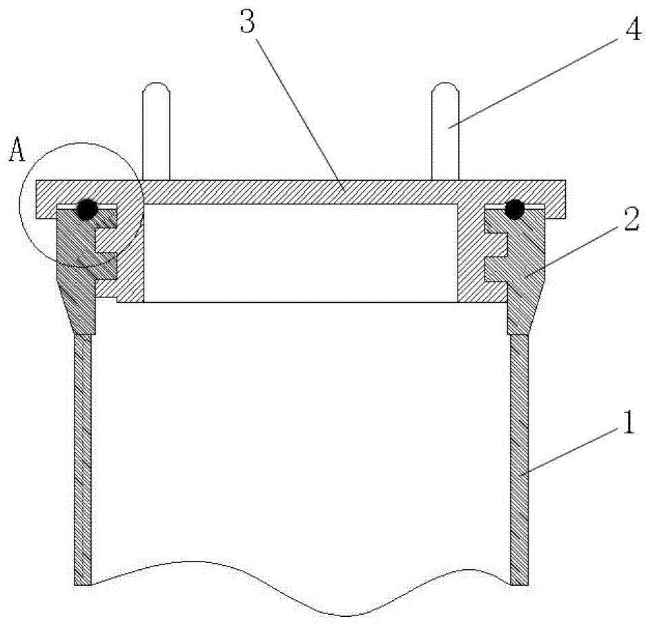
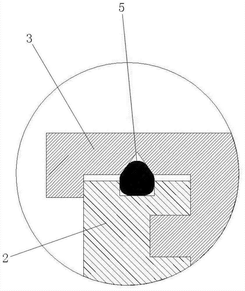
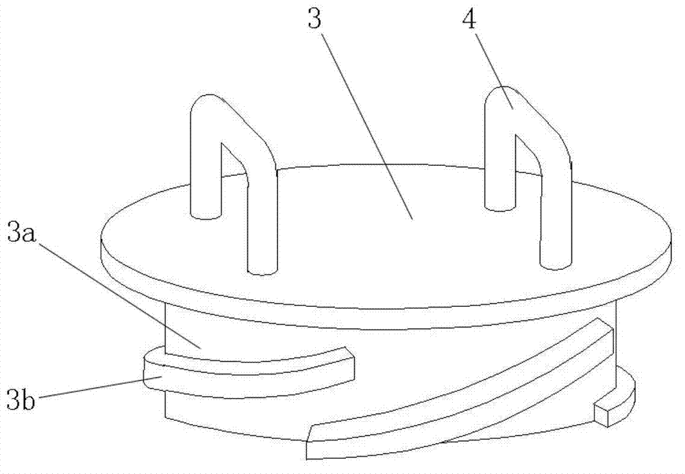
[0019] Reference attached figure 1 Attached Figure 5 , An anti-explosive container sealing structure, the structure of the anti-explosive container sealing structure includes an anti-explosive container body 1, a collar 2 and a cover 3, wherein the collar 2 is in the shape of a circular ring, and the collar 2 is fixed on the anti-explosive container At the opening of the container body 1, the top plane of the collar 2 is provided with an annular groove 2a, and the inner side of the collar 2 is provided with a multi-threaded thread 2b; the upper part of the lid 3 is in the shape of a disc, and the lower part of the lid 3 is cylindrical or Cylindrical shape, with a handle 4 on the top surface of the upper part of the cover 3, a retaining ring 3c on the side surface of the upper part of the cover 3, and a multi-threaded thread on the inner surface of the collar 2 on the outer surface of the lower part 3a of the cover 2b matching multi-threaded two 3b; on the bottom surface of the...

Embodiment 2

[0021] Reference attached figure 1 Attached Figure 5 , An anti-explosive container sealing structure, the structure of the anti-explosive container sealing structure includes an anti-explosive container body 1, a collar 2 and a cover 3, wherein the collar 2 is in the shape of a circular ring, and the collar 2 is fixed on the anti-explosive container At the opening of the container body 1, the top plane of the collar 2 is provided with an annular groove 2a, the inner side of the collar 2 is provided with a multi-threaded thread 2b, and a spring is provided on the thread 2b on the inner side of the collar 2 sheet. The rest of the structure is the same as the first embodiment.


PUM


Abstract

The invention relates to an antiknock container sealing structure which comprises an antiknock container body, an annular sleeve ring and a cover, wherein the sleeve ring is fixed at the position of an opening of the antiknock container body; a first circular groove is arranged on a top plane of the sleeve ring, and a first thread is arranged on an inner lateral face of the sleeve ring; the upper portion of the cover is disc-shaped, the lower portion of the cover is column-shaped or cylindrical, a handle is arranged on a top face of the upper portion of the cover, a retaining ring is arranged on a lateral face of the upper portion of the cover, and a second thread matched with the first thread on the inner lateral face of the sleeve ring is arranged on an outer lateral face of the lower portion of the cover; a second circular groove anastomotic with the first circular groove on the top plane of the sleeve ring is arranged on a disc-shaped bottom surface of the upper portion of the cover; and a sealing ring is arranged in an annular hole formed by the first circular groove on the top plane of the sleeve ring and the second circular groove on the disc-shaped bottom face of the upper portion of the cover. With the adoption of an antiknock container using the sealing structure, electrostatic induction and electromagnetic induction can be shielded; and the an antiknock container has the advantages of saving labor and being convenient during operation of closing a top cover of the antiknock container.

Description

Technical field [0001] The invention relates to the technical field of anti-explosive containers, in particular to a sealing structure capable of shielding electrostatic induction and electromagnetic induction in an anti-explosive container. Background technique [0002] The main reason for the detonation of electric detonators is electrostatic induction and electromagnetic induction. When placing an electric detonator in an anti-explosion container, if the inner cavity of the anti-explosion container is subjected to static or electromagnetic induction, the electric detonator placed in the anti-explosion container will detonate. At present, there is no report on the anti-explosive container with a sealing structure capable of shielding electrostatic induction and electromagnetic induction. In addition, the existing connection between the top cover of the anti-explosive container and the cylinder body generally adopts a bayonet and single-threaded connection method. When the bayo...

Claims


Application Information

Patent Timeline
IPC IPC(8): B65D55/06
Inventor 蒋友明
Owner 蒋友明
Why Eureka
Try Eureka