Orthogonal I/O (Input/Output) signal phase unbalance correcting circuit

A technology for correcting circuits and signal phases, applied to transmitter/receiver shaping networks, baseband system components, etc., can solve problems such as bandwidth limitations, inability to achieve correction coefficients, and difficulty in achieving high precision

Active Publication Date: 2013-01-09
中科芯未来微电子科技成都有限公司
View PDF4 Cites 12 Cited by
  • Summary
  • Abstract
  • Description
  • Claims
  • Application Information

AI Technical Summary

Problems solved by technology

This method uses the ratio of the resistance to achieve the correction coefficient. Due to the limitation of the resistance value, i

Method used


Image

  • Orthogonal I/O (Input/Output) signal phase unbalance correcting circuit
  • Orthogonal I/O (Input/Output) signal phase unbalance correcting circuit
  • Orthogonal I/O (Input/Output) signal phase unbalance correcting circuit

Examples


Embodiment Construction

[0030] The technical solutions of the present invention will be further specifically described below through embodiments in conjunction with the accompanying drawings.

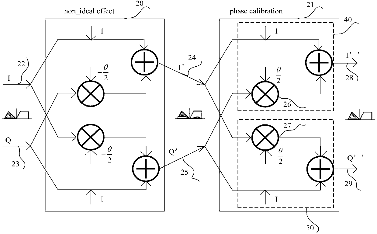
[0031] Assuming ideal quadrature I / Q signals are I ideal = cosωt, Q ideal =sinωt, t represents time, and ω is the angular frequency of the signal. The non-ideal I / Q signals after introducing the phase mismatch θ are respectively Q ′ = sin ( ωt - θ 2 ) . Expressed in matrix form as:

[0032] I ′ Q ′ = 1 - θ ...


PUM


Abstract

The invention provides a high-precision I/O (Input/Output) signal phase unbalance correcting circuit in a low-intermediate frequency wireless receiver. The high-precision I/O signal phase unbalance correcting circuit achieves the high image rejection requirement. According to the high-precision I/O signal phase unbalance correcting circuit, an I-path signal and a Q-path signal are coupled by a current summing circuit by adopting a matrix coupling circuit, and therefore phase unbalance correction is realized in the coupling process, wherein the coupling coefficient determines the magnitude of correction scope. According to the invention, an upper matrix coupling circuit is realized by adopting a method of intersecting two groups of geminate transistors, and the coupling coefficient is controlled by a variable current source and a fixed current source. The variable current source is realized by an 8-bit current-type DAC (Digital-to-Analog Converter). The high-precision I/O signal phase unbalance correcting circuit can be used for correcting the phase deviation precisely, wherein the correcting precision is up to 0.04 DEG, the correcting scope is +/-7DEG, and magnitude unbalance is not caused. The high-precision I/O signal phase unbalance correcting circuit is free from a high-precision ADC (Analog-to-Digital Converter) module and a high-performance DSP (Digital Signal Processor) chip, simple in implementation method, high in integration level and greatly-reduced in power consumption.

Description

technical field [0001] The invention relates to a quadrature I / Q signal phase unbalance correction circuit in a low-intermediate frequency wireless receiver, and belongs to the technical field of wireless communication integrated circuits. Background technique [0002] The low-IF wireless receiver combines the advantages of the superheterodyne receiver and the zero-IF receiver. It not only has a high degree of integration, but also makes low cost and low power consumption possible. At the same time, it avoids the flicker noise and Effect of DC offset. However, there is a problem of image signal interference in low-IF receivers. After quadrature down-conversion by the mixer, the useful signal and the image signal are located at the positive frequency (f IF ) and negative frequencies (-f IF ), a complex filter with an asymmetric amplitude-frequency response is usually used to suppress the image signal. However, the image rejection capability of the complex filter strongly ...

Claims


Application Information

Patent Timeline
IPC IPC(8): H04L25/02H04L25/03
Inventor 项勇甘业兵马成炎
Owner 中科芯未来微电子科技成都有限公司
Why Eureka
Try Eureka