Introducer sheath, placement device for blood vessel treatment instrument, and method for shortening introducer sheath

A technology of guiding sleeves and blood vessels, applied in the field of guiding sleeves, can solve problems such as inability to use therapeutic equipment and the like

Inactive Publication Date: 2013-01-09
TERUMO KK
View PDF6 Cites 4 Cited by
  • Summary
  • Abstract
  • Description
  • Claims
  • Application Information

AI Technical Summary

Problems solved by technology

Therefore, when the outer tube of the system is directly used as a guide sleeve when inserting other treatment equipment, the treatment equipment needs to have the entire length of the out

Method used


Image

  • Introducer sheath, placement device for blood vessel treatment instrument, and method for shortening introducer sheath
  • Introducer sheath, placement device for blood vessel treatment instrument, and method for shortening introducer sheath
  • Introducer sheath, placement device for blood vessel treatment instrument, and method for shortening introducer sheath

Examples


Embodiment Construction

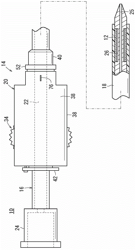
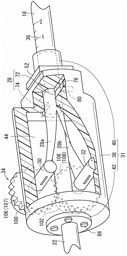
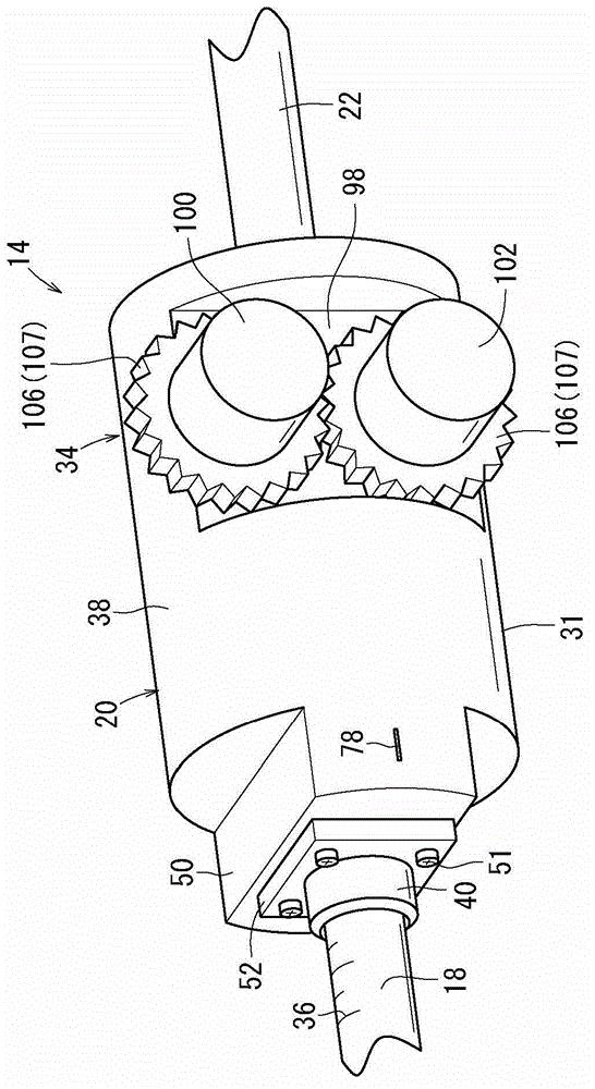
[0035] Below, the preferred embodiment is listed for the indwelling device of the guide sheath, the vascular treatment tool and the shortening method of the guide sheath of the present invention, while referring to the attached Figure 1 side to explain it. In addition, for the convenience of explanation, the figure 1 , Figure 4 , Figure 5 The right side in the is called the "front end" and the figure 1 , Figure 4 , Figure 5 The left side in is called the "base end (rear end)", and the figure 2 The upper right side in is called the "Front End" and the figure 2 The lower left side in is called the "base end (rear end)", and the image 3 The lower left side in is called the "Front End" and the image 3 The upper right side in is called the "basal end (posterior end)".

[0036] figure 1The shown indwelling device 10 of the vascular treatment tool (hereinafter also referred to simply as "the indwelling device 10") is used to deliver and indwell the stent-graft 12 a...


PUM


Abstract

A placement device (10) for a blood vessel treatment instrument has an introducer sheath (14) functioning as an outer tube, and also has an inner tube (16). The introducer sheath (14) has a flexible, tube-shaped sheath body (18) and a hub (20) into which the base end of the sheath body (18) is inserted. The hub (20) takes up the base end of the sheath body (18) into the hub (20) by means of winding shafts (30, 32) while tearing the base end of the sheath body (18) by cutting blades (72, 74), and thus the length of extension of the sheath body (18) from the hub (20) can be reduced.

Description

technical field [0001] The present invention relates to a guide sleeve capable of shortening the entire length, an indwelling device for a blood vessel treatment tool, and a shortening method of the guide sleeve. Background technique [0002] Generally, when a catheter is inserted into a blood vessel for diagnosis and treatment, the introducer sleeve is used as an access route for connecting the outside of the body and the inside of the blood vessel. The first object is to reduce blood vessel damage caused by multiple insertion and withdrawal of catheters with different diameters in the blood vessel puncture part when a plurality of catheters are used sequentially. The second object is to facilitate insertion and avoid blood vessel damage when inserting a catheter having an uneven surface such as a large-diameter balloon catheter or a balloon-expandable stent. [0003] On the other hand, in the case of a stent-graft system (also called a stent-graft system, stent-graft syst...

Claims


Application Information

Patent Timeline
IPC IPC(8): A61M25/08A61F2/962
CPCA61M25/01A61M25/0668A61F2/97A61M25/1002A61M2025/0681A61F2/962A61M25/0097A61M2025/0675A61F2/9517
Inventor 泽田明
Owner TERUMO KK
Why Eureka
Try Eureka