Atraumatic Tip Geometry For Indwelling Devices

a technology of indwelling devices and tip geometry, which is applied in the field of indwelling devices to achieve the effects of minimizing the morbidity of distraction therapy, maximizing bowel length gain, and improving the safety profile of any endoluminal devi

Active Publication Date: 2016-07-28
RGT UNIV OF MICHIGAN
View PDF9 Cites 2 Cited by
  • Summary
  • Abstract
  • Description
  • Claims
  • Application Information

AI Technical Summary

Benefits of technology

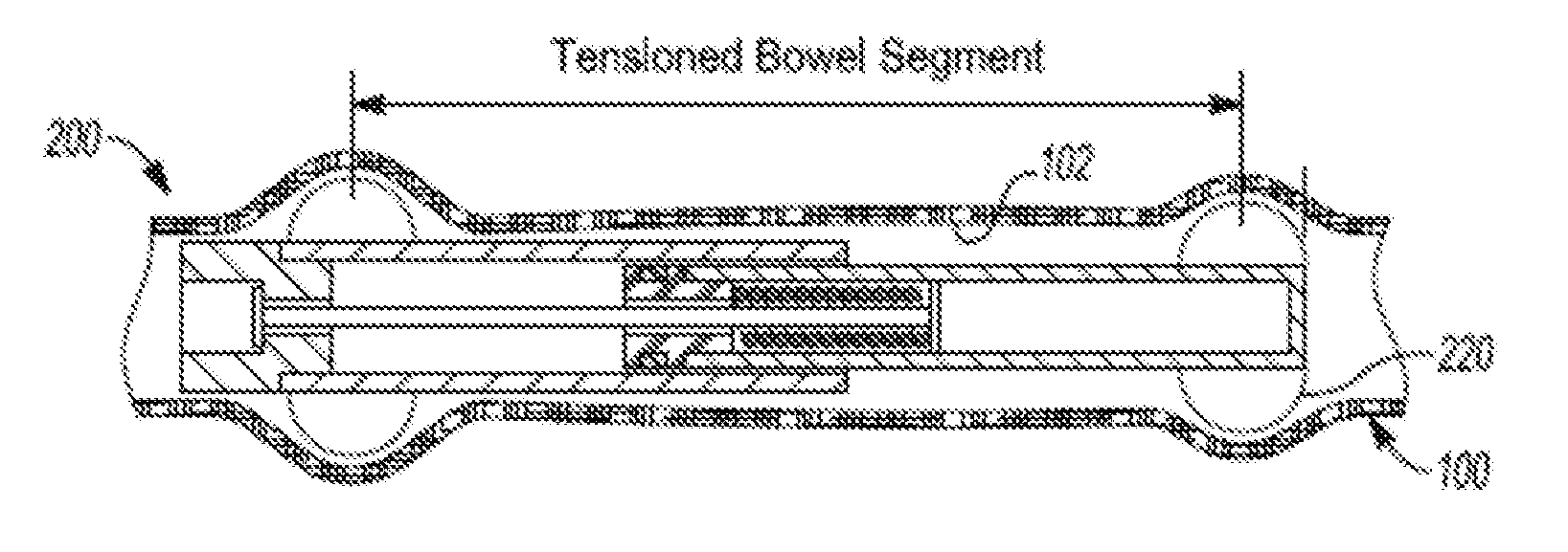
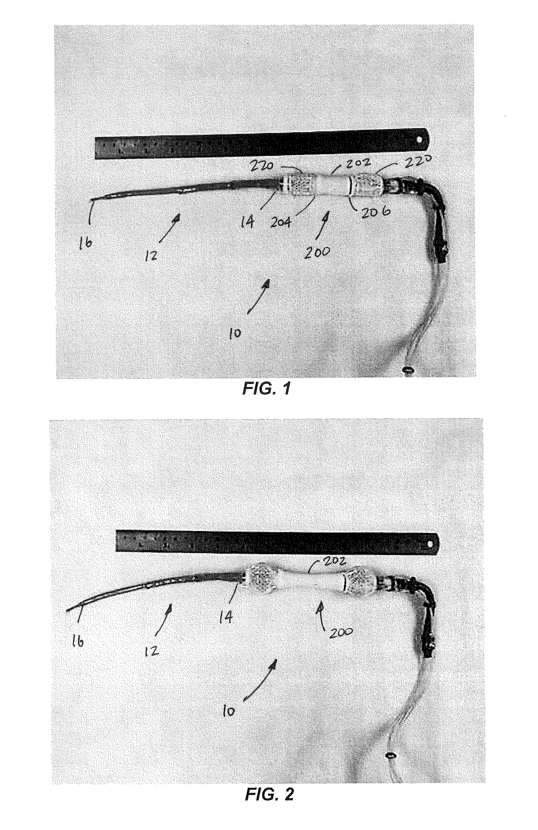
[0078]Clinically applicable distraction enterogenesis requires maximizing bowel length gain while minimizing the morbidity of the distraction therapy. A fully endoluminal device may achieve this goal by allowing distraction without multiple operations. The present teachings demonstrate a method of and apparatus for endoluminal distraction enterogenesis using an indwelling, semirigid device with an atraumatic geometry of the end of the device. This strategy provides an effective method of intestinal attachment via geometric coupling of the device and mesenteric curvature. In addition, this geometry may improve the safety profile of any endoluminal device that is stiff relative to the bowel. Because the small intestine is nonlinear in orientation with the mesentery tethering the bowel in a curved course, an endoluminal device must conform to this curvilinear shape.
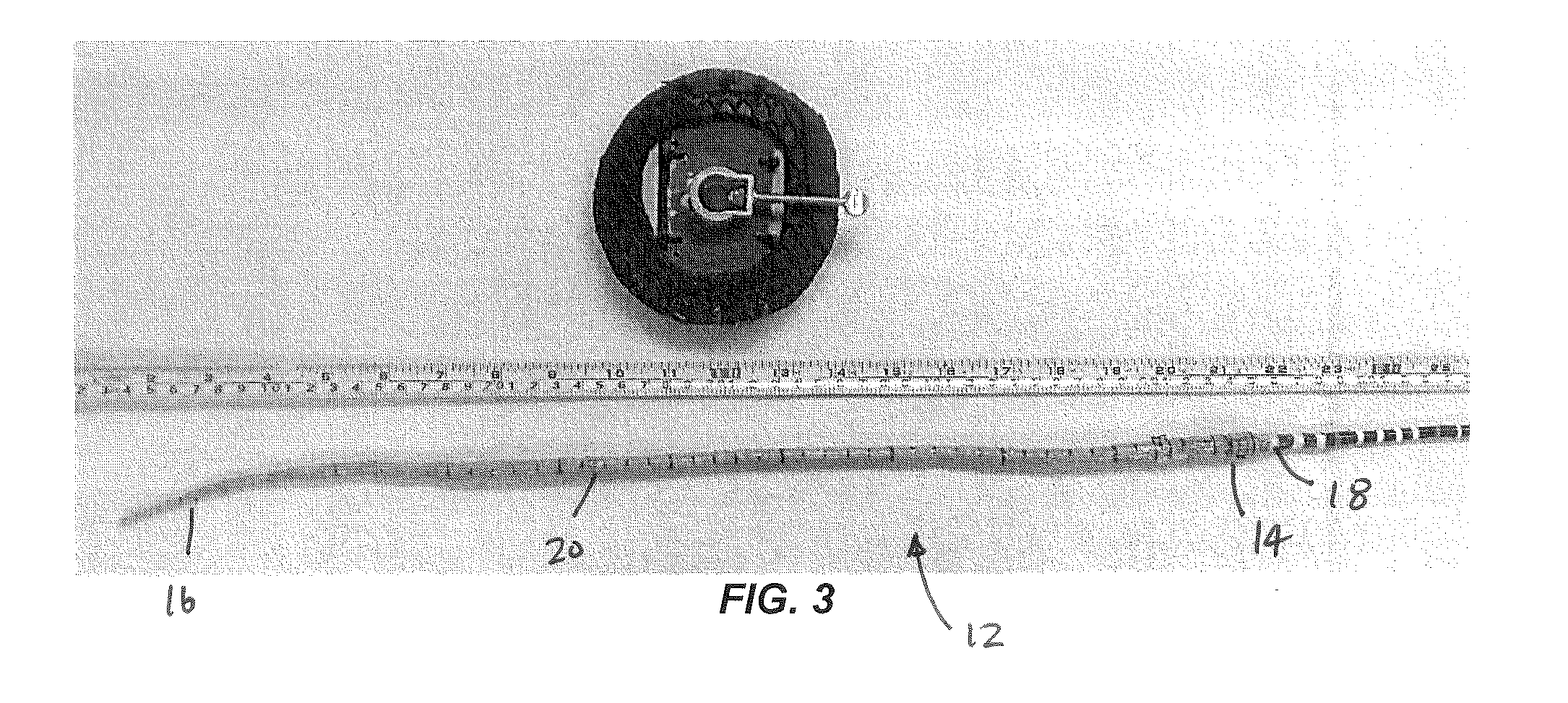
[0079]Devices that are stiff relative to the bowel, therefore, exert outward radial force on the small bowel and its mesentery (unless constructed to exactly match the bowel radius of curvature). At the end of a semirigid device, the bowel bends sharply over the device tip. This bending may create a focal point of radial force on the bowel, potentially inducing focal bowel ischemia and perforation. This phenomenon has been noted in a catheter-based endoluminal distraction enterogenesis device previously, and it may explain reports of delayed perforation from the ends of enteric feeding tubes. The gradual taper in stiffness of this device allowed for the catheter to exert progressively less radial force on the antimesenteric bowel wall as it approached the end of the device, preventing a sharp bend in the bowel over the end of the device, thereby decreasing the risk of perforation.
[0080]This method of distraction enterogenesis required an enterostomy for device insertion. Trans-stomal distraction enterogenesis has been described, although this technique relied on end-abutment of a stiff device on a surgically created intestinal blind end. Although such anatomy is not encountered frequently clinically, enterostomies and / or mucus fistulae often are present in patients with SBS. Trans-stomal distraction enterogenesis using geometric attachment may be a viable method of increasing residual bowel length in these patients. For example, such a device may be placed for a course of distraction therapy before takedown of the enterostomy in a patient who has undergone massive bowel resection and is at risk of SBS. This approach may allow the reversal of disuse atrophy if used via a mucous fistula, may induce substantial gain of length before takedown of the enterostomy with reanastomosis, and would not require additional operative maneuvers.

Problems solved by technology

Previously described methods have relied upon isolated intestinal segments or transmural fixation due to ineffective endoluminal attachment.

Method used


Image

  • Atraumatic Tip Geometry For Indwelling Devices
  • Atraumatic Tip Geometry For Indwelling Devices
  • Atraumatic Tip Geometry For Indwelling Devices

Examples


Embodiment Construction

[0025]Example embodiments will now be described more fully with reference to the accompanying drawings. Example embodiments are provided so that this disclosure will be thorough, and will fully convey the scope to those who are skilled in the art. Numerous specific details are set forth such as examples of specific components, devices, and methods, to provide a thorough understanding of embodiments of the present disclosure. It will be apparent to those skilled in the art that specific details need not be employed, that example embodiments may be embodied in many different forms and that neither should be construed to limit the scope of the disclosure. In some example embodiments, well-known processes, well-known device structures, and well-known technologies are not described in detail.

[0026]The terminology used herein is for the purpose of describing particular example embodiments only and is not intended to be limiting. As used herein, the singular forms “a,”“an,” and “the” may b...


PUM


Abstract

An indwelling device for insertion in a biological tubular structure comprising an elongated device having a body and opposing ends. The body has a bending stiffness transverse to a longitudinal axis that is greater than a stiffness of the biological tubular structure. An atraumatic tip member, having a proximal end and a distal end, extends from the end of the elongated device. The proximal end has a first bending stiffness transverse to a longitudinal axis and the distal end has a second bending stiffness transverse to the longitudinal axis, wherein the second bending stiffness being less than the first bending stiffness.

Description

CROSS-REFERENCE TO RELATED APPLICATIONS[0001]This application is a continuation-in-part of U.S. patent application Ser. No. 14 / 718,175 filed on May 21, 2015. This application claims the benefit of U.S. Provisional Application No. 62 / 106,859, filed on Jan. 23, 2015. The entire disclosure of the above applications is incorporated herein by referenceGOVERNMENT INTEREST[0002]This invention was made with government support under FD003787 awarded by the Food and Drug Administration. The government has certain rights in the invention.FIELD[0003]The present disclosure relates to indwelling devices and, more particularly, relates to an atraumatic tip geometry having tapering stiffness allowing for atraumatic placement of an indwelling device inserted in biological tubular structures.BACKGROUND AND SUMMARY[0004]This section provides background information related to the present disclosure which is not necessarily prior art. This section provides a general summary of the disclosure, and is not...

Claims


Application Information

Patent Timeline
Patent Type & Authority Applications(United States)
IPC IPC(8): A61F2/04
CPCA61F2/04A61F2002/045A61F2250/001A61F2250/0069A61F2250/0029A61F2250/0059A61F2250/0018A61B17/02A61B17/12045A61B2017/00557A61B2017/00818A61B2017/12127A61M29/02
Inventor DEMEHRI, FAROKH R.TEITELBAUM, DANIEL H.LUNTZ, JONATHAN E.UTTER, BRENTBREI, DIANN ERBSCHLOEFREEMAN, JENNIFER
Owner RGT UNIV OF MICHIGAN
Why Eureka
Try Eureka