
Up-mounted advancing mechanism and thin coal seam hydraulic support

A technology of pushing mechanism and hydraulic support, which is applied in mine roof support, mining equipment, earthwork drilling and mining, etc. It can solve the problems of difficult free design of support pushing mechanism and low working resistance of the minimum height of support.

Inactive Publication Date: 2013-01-16
CHINA COAL BEIJING COAL MINING MACHINERY
View PDF9 Cites 0 Cited by
  • Summary
  • Abstract
  • Description
  • Claims
  • Application Information

AI Technical Summary

Problems solved by technology

[0002] In the prior art, there are mainly two types of moving mechanisms for thin coal seam hydraulic supports. One is the formal installation of the pushing jack. In the case of a high minimum height of the support or low working resistance; the other is to learn from the form of the foreign thin coal seam support push mechanism, connect the "bow" plate between the left and right bases of the support, and connect the push jack with the push rod. This form is multi-purpose For the hydraulic support on the working face of the coal plow, when the working resistance of the support is large and the minimum height is low, it is often difficult to freely design the support moving mechanism due to structural constraints

Method used


Image

  • Up-mounted advancing mechanism and thin coal seam hydraulic support
  • Up-mounted advancing mechanism and thin coal seam hydraulic support
  • Up-mounted advancing mechanism and thin coal seam hydraulic support

Examples


specific Embodiment approach

[0016] The preferred embodiment of the dress pushing mechanism of the present invention is:

[0017] It includes a front pushing rod, a pushing jack, and a rear pushing rod. The front pushing rod is provided with a round steel guide rail, and the rear pushing rod is provided with a steel pipe slideway, and the round steel guide rail is inserted into the steel pipe slideway , the front end of the pushing jack is connected with the front pushing rod, and the rear end of the moving jack is connected with the rear pushing rod.

[0018] The front pushing rod is connected and fixed with the round steel guide rail, and the inner side of the middle part of the round steel guide rail is provided with a connecting ear plate, which is connected with a connecting head, and the rear end of the connecting head is connected with the piston of the pushing jack. Rod front connection;

[0019] The cylinder body of the pushing jack is provided with a fixed ear plate, which is connected with the...

specific Embodiment

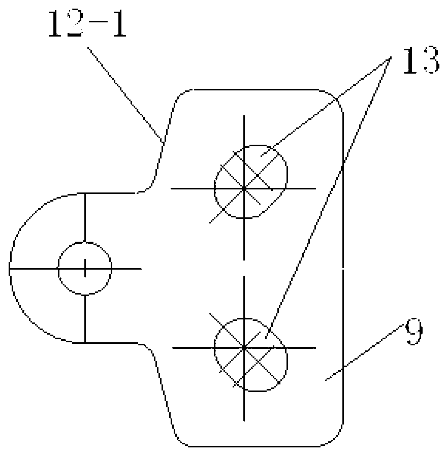
[0027] Such as figure 1 , figure 2 Shown, the front portion pushing rod 1 is connected and fixed with the round steel guide rail 4 by the bearing pin 5-1, and each side of the bearing pin 5-1 can be two or more pieces. The inner side of the middle part of the round steel guide rail 4 is welded with a connecting lug plate, which is connected to the connecting head 8 through the pin shaft 5-2. The piston rod end of 3 is connected; the rear part of the round steel guide rail 4 is inserted into the steel pipe slideway 7 of the rear push rod 2, and can slide back and forth in the slideway, and the cylinder body of the push jack 3 is welded with a fixed lug plate. The plate is connected with the rear pushing bar 2 and fixed with a pressing plate 6;

[0028] Such as image 3 , Figure 4 , Figure 5 As shown, the rear end of the rear pushing rod 2 has a group of ear plates, which are connected with the single hole at the front end of the connecting plate 9 through the pin shaft ...


PUM


Abstract

The invention discloses an up-mounted advancing mechanism and a thin coal seam hydraulic support. The up-mounted advancing mechanism comprises a front advancing rod, an advancing jack and a rear advancing rod, wherein the front advancing rod is provided with a round steel guide rail; the rear advancing rod is provided with a steel pipe slipway; the round steel guide rail is inserted into the steel pipe slipway; and the front end of the advancing jack is connected with the front advancing rod, and the rear end of the advancing jack is connected with the rear advancing rod. When the advancing jack is pushed inwards to make liquid flow back, the advancing rod is extended or retracted, and frame pulling and pushing slip cyclic actions are finished by the support; and the mechanism can adapt to high working resistance and the thin coal seam hydraulic support.

Description

technical field [0001] The invention relates to a hydraulic support for a fully mechanized coal mining face in a thin coal seam, in particular to a positively installed moving mechanism and a thin coal seam hydraulic support. Background technique [0002] In the prior art, there are mainly two types of moving mechanisms for thin coal seam hydraulic supports. One is the formal installation of the pushing jack. In the case of a high minimum height of the support or low working resistance; the other is to learn from the form of the foreign thin coal seam support push mechanism, connect the "bow" plate between the left and right bases of the support, and connect the push jack with the push rod. This form is multi-purpose For the hydraulic support on the working face of the coal plow, when the working resistance of the support is large and the minimum height is low, it is often difficult to freely design the support moving mechanism due to structural constraints. Contents of th...

Claims


Application Information

Patent Timeline
IPC IPC(8): E21D23/18E21D23/04
Inventor 贾一
Owner CHINA COAL BEIJING COAL MINING MACHINERY
Learn More