Hydraulic support push rod

A technology of hydraulic supports and push rods, which is applied in pillars/supports, mining equipment, earthwork drilling and mining, etc. It can solve the problems of easy opening of welds, decreased strength, and low safety factor, so as to improve strength and service life, and manufacture The effect of simple process and high safety factor

Inactive Publication Date: 2007-01-03
四川航天神坤装备有限公司
View PDF1 Cites 0 Cited by
  • Summary
  • Abstract
  • Description
  • Claims
  • Application Information

AI Technical Summary

Problems solved by technology

The push rod of the pressure bracket currently used is usually welded with steel plates to form a box structure. In a working environment with high working resistance, this kind of push rod is easy to break and the weld seam is easy to pull apart.
For high-strength, high-resistance, high-reliability hydraulic supports, the yield point used for the push rods is above 1200Mpa, the welding process of low-alloy high-strength steel is extremely complicated and difficult, and the strength of the heat-affected zone decreases to a certain extent. resulting in a lower safety factor

Method used


Image

  • Hydraulic support push rod
  • Hydraulic support push rod

Examples


Embodiment Construction

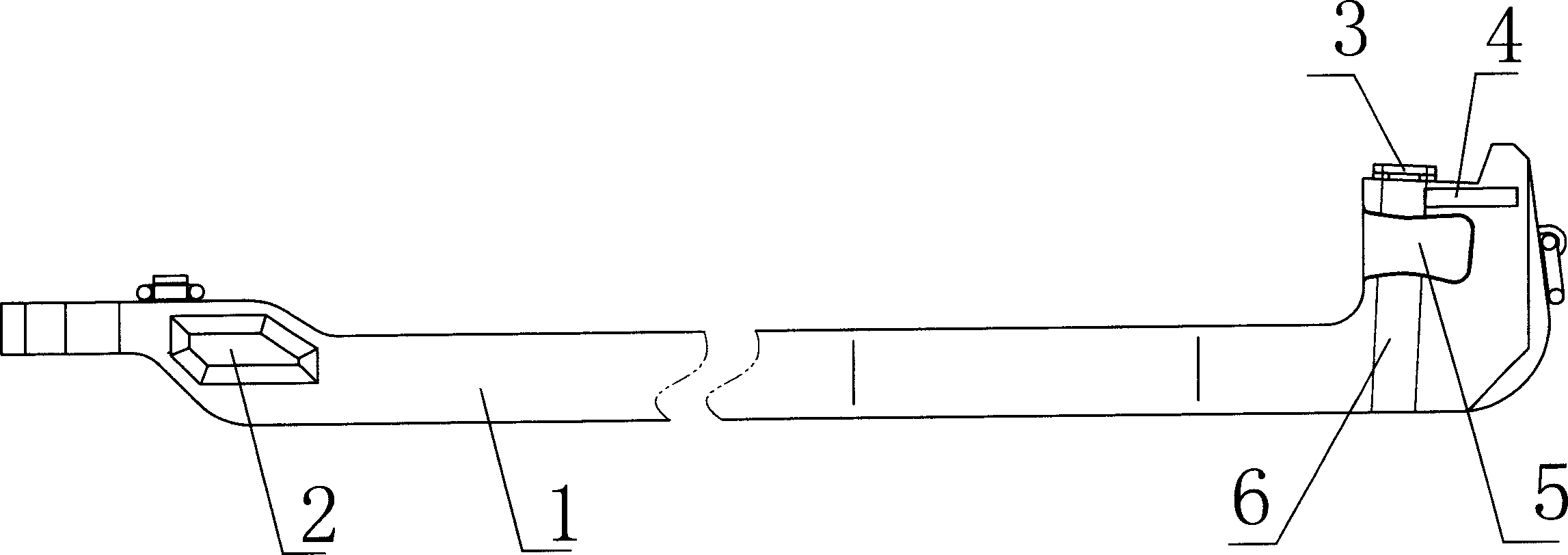
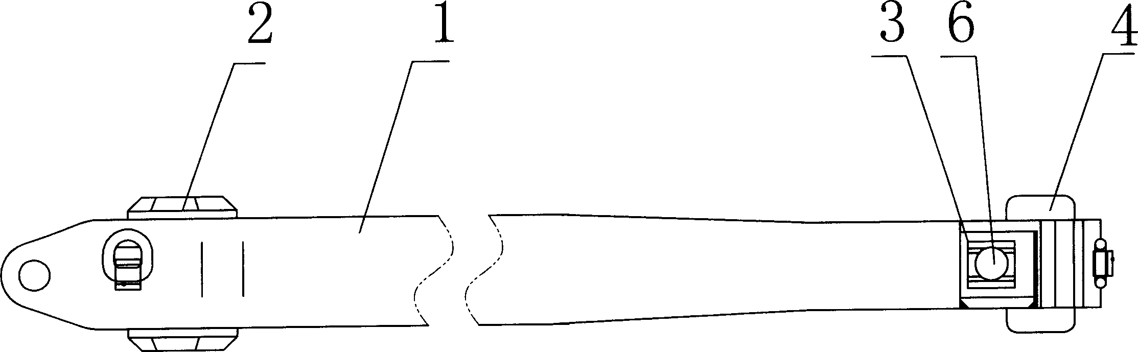
[0012] like figure 1 , figure 2 As shown, a hydraulic support push rod includes a push rod body 1 and reinforcement blocks 2 welded on both sides of the head of the push rod body 1, and a limit block 3 welded on the tail of the push rod body 1, which is welded on the push rod The guide plates 4 on both sides of the tail of the body 1, wherein the limit block 3 is provided with a pin hole 6, and the pin hole 6 runs through the tail of the push rod body 1, and the pin hole 6 is used to limit the connecting pin shaft, push The rod body 1 is forged as a whole. In order to solve the processing problem of the connecting notch between the tail of the push rod body and the push jack, during the forging process of the push rod body, one side of the notch at the tail of the push rod body 1 is opened, and after forging Carry out seal welding with paster plate 5. In use, push the base of the jack into the notch. The push rod is made of alloy structural steel with a yield point higher ...


PUM


Abstract

The present invention discloses a hydraulic support push-rod, belonging to the field of coal mining working face corollary equipment hydraulic support technology. It includes push-rod body and reinforcing blocks respectively welded on two sides of push-rod body head portion, spacing block welded in the upper portion of push-rod body tail portion and guide plates respectively welded on two sides of push-rod body tail portion.

Description

technical field [0001] The invention relates to a hydraulic support for supporting equipment in fully mechanized mining working faces of coal mines, in particular to a hydraulic support push rod. Background technique [0002] The push rod in the hydraulic support is located in the middle space of the base, placed on the bottom plate, and connected with the moving jack and the connecting head through the pin shaft to form a moving device, so as to realize the movement of the support itself and the conveyor. Therefore, the push rod in the hydraulic support is an important force-bearing part for the hydraulic support to push the working face conveyor and push the hydraulic support. In addition to bearing the axial force, it also bears the vertical and horizontal lateral forces. The force situation is relatively bad. Very fragile. The push rod of the pressure bracket currently used is usually welded by steel plates to form a box structure. In a working environment with high wor...

Claims


Application Information

Patent Timeline
Patent Type & Authority Applications(China)
IPC IPC(8): E21D15/54
Inventor 庞季洪陈建先颜珉刘水章花向阳
Owner 四川航天神坤装备有限公司
Why Eureka
Try Eureka