Positioning support device used for stirring, rubbing and welding circular seam of flange disc of top cover of storage box

A technology of positioning support and stirring friction, which is applied in welding equipment, non-electric welding equipment, metal processing equipment, etc., can solve the problems of increased difficulty in flange ring seam welding, poor resistance to deformation, and difficult assembly, etc., to achieve small deformation , high joint quality and simple structure

Active Publication Date: 2013-01-23
CAPITAL AEROSPACE MACHINERY +1
View PDF5 Cites 27 Cited by
  • Summary
  • Abstract
  • Description
  • Claims
  • Application Information

AI Technical Summary

Problems solved by technology

[0004] The welding difficulty of this large thin-walled structural part lies in that the welding area is relatively thin, and the thickness of the welding area of ​​the thinnest shell section is 3.7mm; the structural size is large, the rigidity of the box is poor, the resistance to deformation is poor, and the assembly is extremely difficult; the above situation makes The difficulty of welding the ring seam of the flange is greatly increased, and relevant measures need to be taken to solve it

Method used


Image

  • Positioning support device used for stirring, rubbing and welding circular seam of flange disc of top cover of storage box
  • Positioning support device used for stirring, rubbing and welding circular seam of flange disc of top cover of storage box
  • Positioning support device used for stirring, rubbing and welding circular seam of flange disc of top cover of storage box

Examples


Embodiment Construction

[0027] The present invention will be described in further detail below in conjunction with the accompanying drawings and specific embodiments.

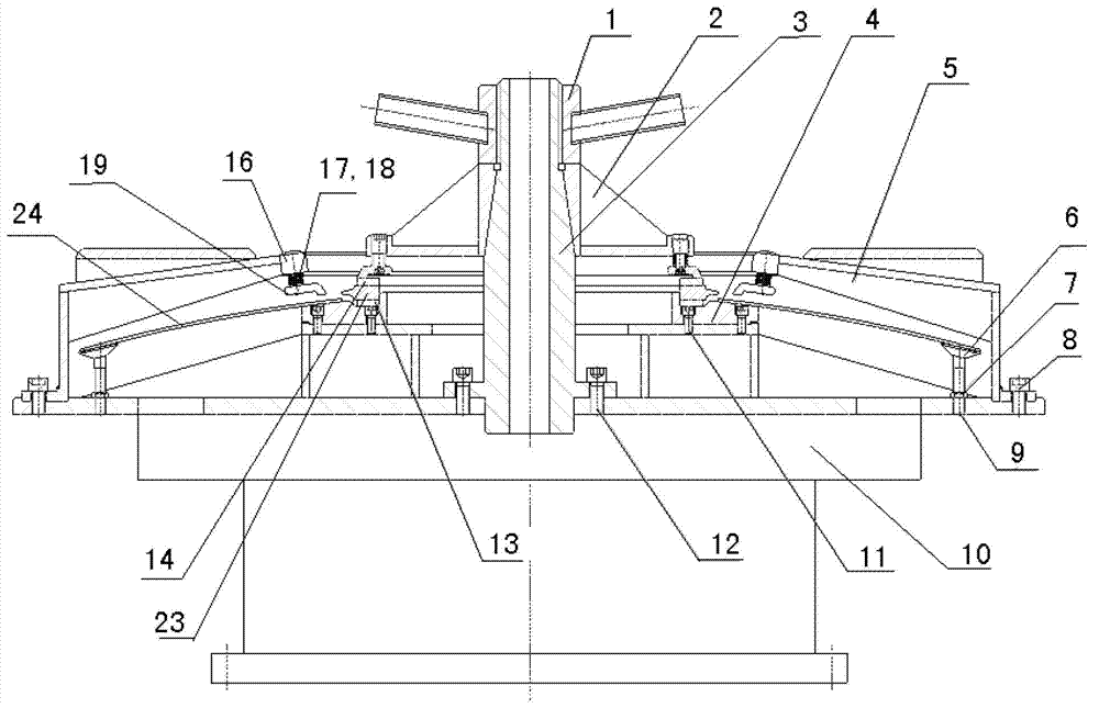
[0028] Such as figure 1 As shown, the center shaft 3 is fixedly installed at the center of the positioning and supporting rotating support 10 by a center shaft positioning bolt 12 . The upper surface of the positioning support rotary support 10 is fixedly installed with a ring-shaped backing plate 4 through a positioning center ring bolt 11 , and the above-mentioned central axis 3 passes through the center of the ring-shaped backing plate 4 .

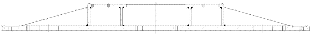
[0029] Such as figure 2 As shown, the positioning support rotating support 10 is an integral welded structure, and there is a mounting hole in the center of the lower bottom surface for installing the above-mentioned central shaft 3, a circular structure is welded on the center of the lower bottom surface, and screw holes are processed on the outer edge of the lower bottom surface.

[0030] ...


PUM


Abstract

The invention belongs to a machining process device of an aerospace product, and in particular discloses a positioning support device used for stirring, rubbing and welding a circular seam of a flange disc of a top cover of a storage box. The machining process device comprises a positioning supporting rotary support, wherein a circular base plate is arranged above the positioning supporting rotary support; an outer pressing ring is arranged above the circular base plate; round holes coaxial with a central hole at the lower bottom surface of the positioning supporting rotary support are arranged in the circular base plate and a center of the outer pressing ring; a central shaft is arranged inside the hole; the lower end of the central shaft is fixed on the positioning supporting rotary support; an outer clamping ring is arranged on the circular base plate; the outer clamping ring is connected with the outer pressing ring through a fastening structure; and a lock wire nut is arranged at the top end of the central shaft. The outer clamping ring, the outer pressing ring and the unique fastening structure have a positioning clamping function to a whole welding product; the outer clamping ring and the central shaft are concentric so as to have a function of positioning a rotation center; a design of the fastening structure has a transition function to connection of a whole positioning support device in a mode that bearing outer pressure is converted into a clamping force, and thus the machining process device is applicable to requirements on high precision in welding and assembling.

Description

technical field [0001] The invention belongs to aerospace product processing technology equipment, and in particular relates to a positioning support device. Background technique [0002] The propellant tank is the fuel tank of the launch vehicle and has a large diameter The material is thin (3.7mm--7mm), and the structural rigidity is weak. The storage tank is generally welded by structural parts such as front and rear short shells, front and rear bottoms, and middle shell sections. The front and rear bottom covers usually include a tailor-welded structure with a flange and a circular arc top, and the general material is aluminum alloy. [0003] Welding adopts advanced welding methods such as friction stir welding, which require the product to be placed horizontally and rotate along the axis. [0004] The welding difficulty of this large thin-walled structural part lies in that the welding area is relatively thin, and the thickness of the welding area of ​​the thinnest ...

Claims


Application Information

Patent Timeline
Patent Type & Authority Applications(China)
IPC IPC(8): B23K20/26B23K20/12
Inventor 赵衍华李书新郝云飞孔德跃杜岩峰许春芳罗军高培涛赵刚朱平萍
Owner CAPITAL AEROSPACE MACHINERY
Why Eureka
Try Eureka