Plunger pump used for pumping ultralow-temperature liquid nitrogen

An ultra-low temperature, plunger pump technology, applied in the field of plunger pumps, can solve the problems of liquid nitrogen easily endothermic vaporization and other problems

Inactive Publication Date: 2013-01-23
YANTAI JEREH PETROLEUM EQUIP & TECH CO LTD
View PDF4 Cites 111 Cited by
  • Summary
  • Abstract
  • Description
  • Claims
  • Application Information

AI Technical Summary

Benefits of technology

This new type of piston pumps has several technical benefits compared with previous designs such as being less prone to absorbing or losing heat during operation due to their design. They also have improved performance when handling liquids at very low temperatures (<-20°C). Additionally they use an ice coolant instead of refrigeration systems to reduce energy consumption by reducing thermal load on components like motors. These improvements make them better than older versions more efficient while still maintaining good efficiency over longer periods of usage.

Problems solved by technology

This technical issue addressed in this patents relates to improving the performance or reliability of conventional hydropneumatic nitrotrusion generators (NGs) for use at extreme temperatures such as those found during well drilling operations due to their poor thermal response characteristics caused by the liquefied nitrous gases released from them.

Method used


Image

  • Plunger pump used for pumping ultralow-temperature liquid nitrogen
  • Plunger pump used for pumping ultralow-temperature liquid nitrogen

Examples


Embodiment Construction

[0013] The principles and features of the present invention will be described below with reference to the accompanying drawings. The examples are only used to explain the present invention, but not to limit the scope of the present invention.

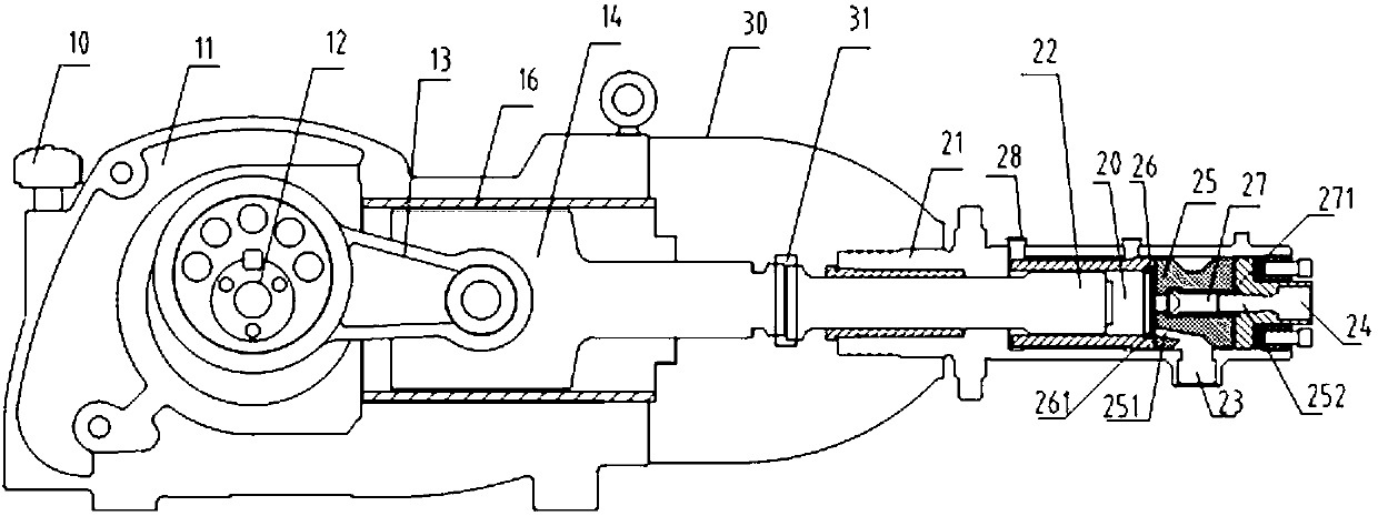
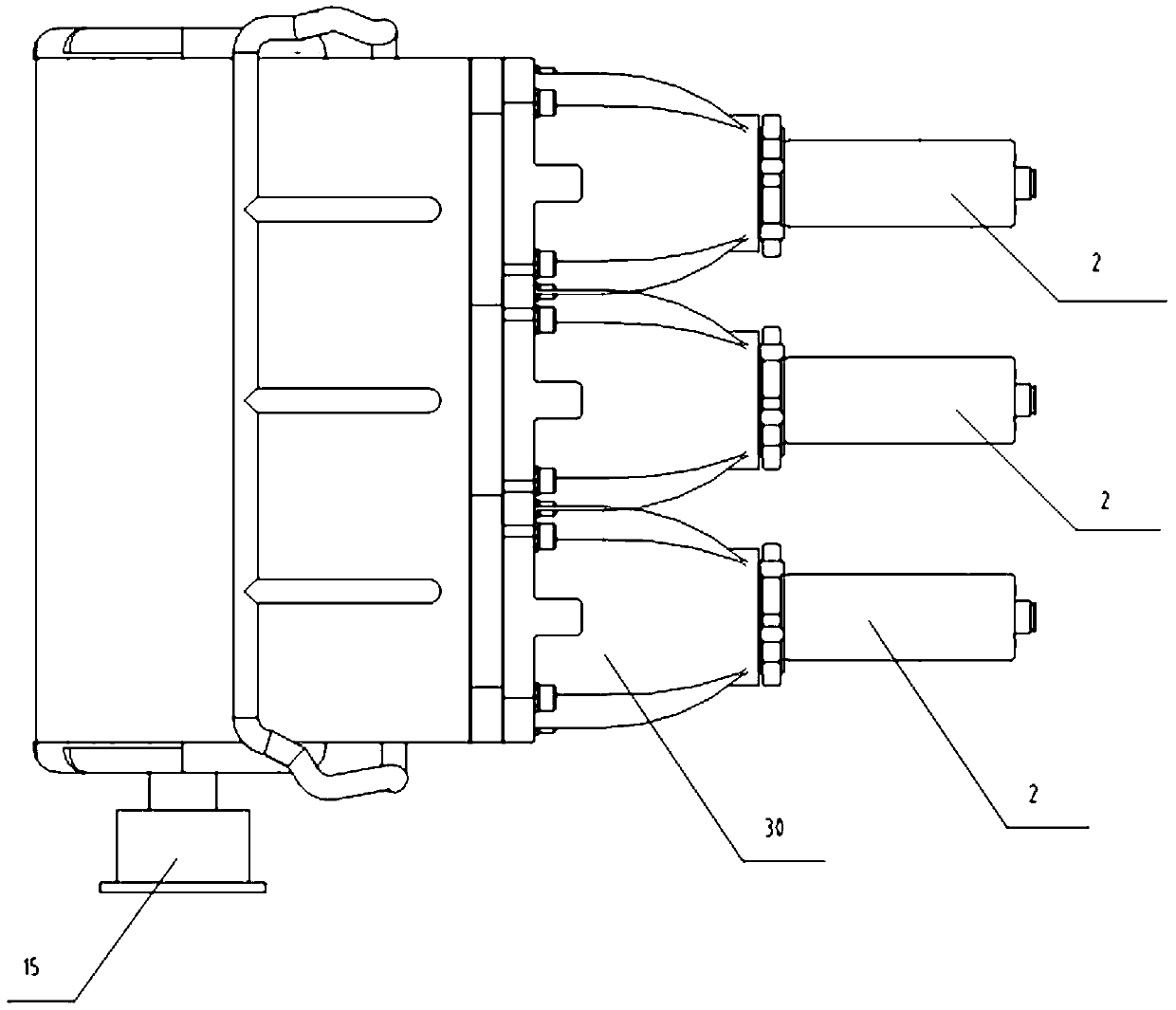
[0014] like figure 1 and figure 2 As shown, a plunger pump for pumping ultra-low temperature liquid nitrogen is mainly composed of two parts, a cold end 2 and a power end. The power end is mainly used to convert the rotary motion transmitted by the engine into reciprocating linear motion. The cold end 2 is the core component of the liquid nitrogen pump, and its interior is professionally designed, and its main function is to achieve low-pressure suction and high-pressure discharge of liquid nitrogen.

[0015] The power end includes a power end housing 11, a crankshaft 12 installed inside the power end housing 11, a connecting rod 13 drivingly connected with the crankshaft 12, and a cross-head tie rod 14 drivingly connected with the c...


PUM


Abstract

The invention relates to a plunger pump used for pumping ultralow-temperature liquid nitrogen, which comprises a power end and a cold end, wherein the cold end comprises a cold end shell; one end of the cold end shell is provided with a plunger; the other end of the cold end shell is provided with a suction inlet and an exhaust port; the positions of the suction inlet and an exhaust port of the cold end shell are provided with a valve seat; one end of the plunger is connected with a power end; the other end of the plunger is mutually matched with the cold end shell and the valve seat to form an inner cavity; the valve seat is provided with a first channel and a second channel, wherein the first channel is used for communicating the inner cavity with the suction inlet; the second channel is used for communicating the inner cavity with the exhaust port; a lower-pressure valve used for controlling the liquid nitrogen to be sucked into the inner cavity is arranged between the first channel and the inner cavity; a high-pressure valve used for controlling the liquid nitrogen to be discharged out of the inner cavity is arranged in the second channel; the plunger is driven by the power end to carry out linear reciprocating motion in the inner cavity so as to drive the lower-pressure valve or the high-pressure valve to be opened and closed; when the low-pressure valve is opened, the liquid nitrogen enters the inner cavity from the suction inlet; when the high-pressure valve is opened, the liquid nitrogen is discharged out of the inner cavity from the exhaust port; and the cold end shell is provided with an overflow port communicated with the inner cavity.

Description


Claims


Application Information

Patent Timeline
Owner YANTAI JEREH PETROLEUM EQUIP & TECH CO LTD
Why Eureka
Try Eureka