
Range hood

A range hood and hood technology are applied in the field of range hoods, which can solve the problems that the power source cannot be aligned with the cooker, the e-liquid rises and overflows, and the oil fume cannot be completely absorbed, so as to prevent the escape of oil fume, easy installation, and improved smoking. effect of effect

Inactive Publication Date: 2013-01-23
谈启明
View PDF8 Cites 6 Cited by
  • Summary
  • Abstract
  • Description
  • Claims
  • Application Information

AI Technical Summary

Problems solved by technology

Its advantage is that, using the principle of eddy current wind pressure, most of the oil fumes that are relatively close to the stove are sucked in the form of an arc, which can reduce the adverse effects on human health, and the power source (fan) is closer to the stove. Basically, it will not reduce the suction effect of the power source (fan); the disadvantage is that the power source (fan) generally cannot be aimed at the stove, which will also cause the oily fume to be completely inhaled. , "Stew" and other cooking methods may even cause smoke oil to rise and overflow

Method used


Image

  • Range hood
  • Range hood
  • Range hood

Examples


no. 1 example

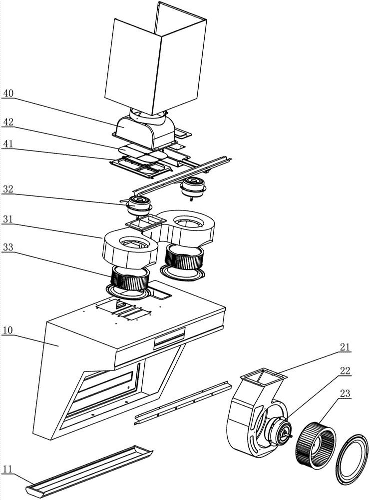
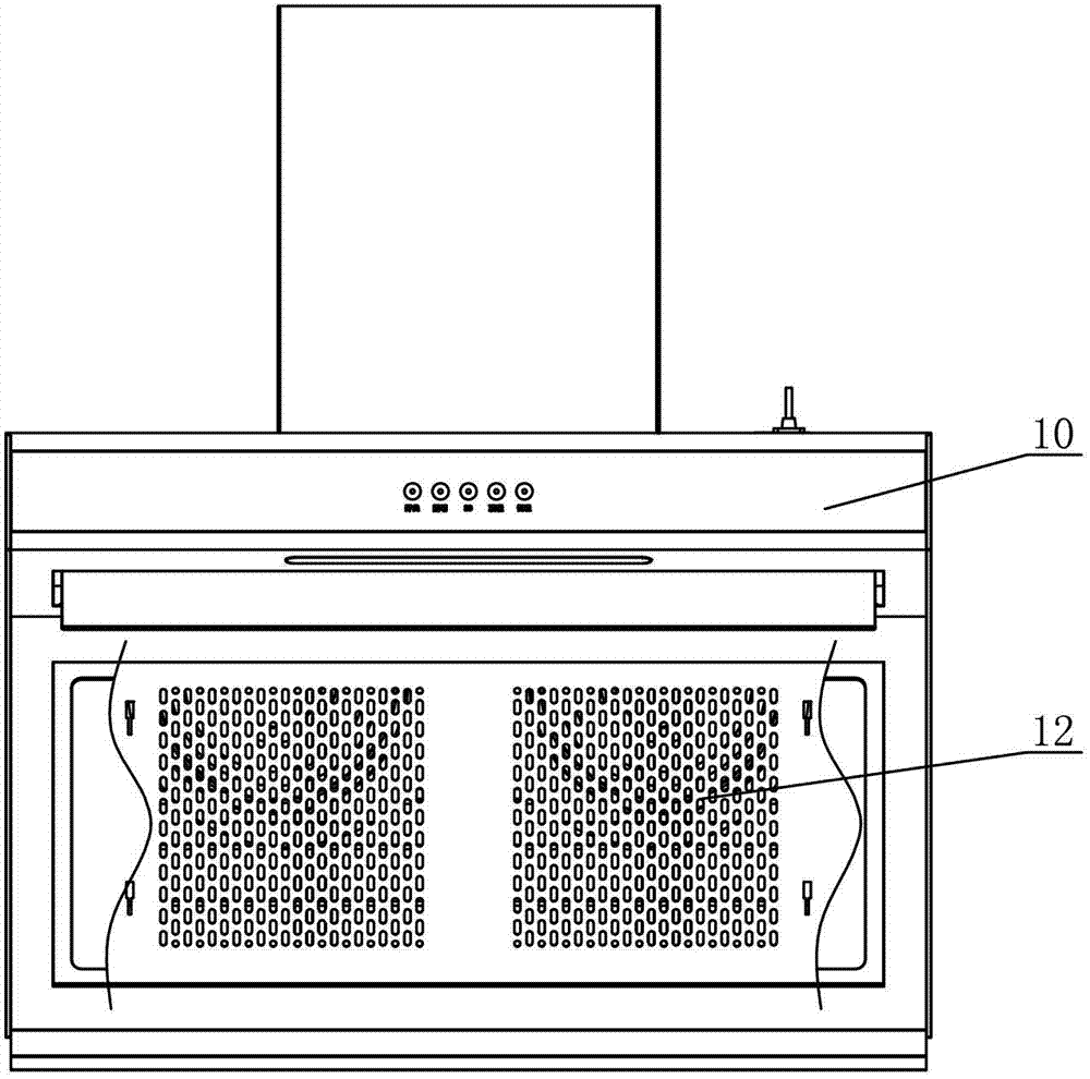
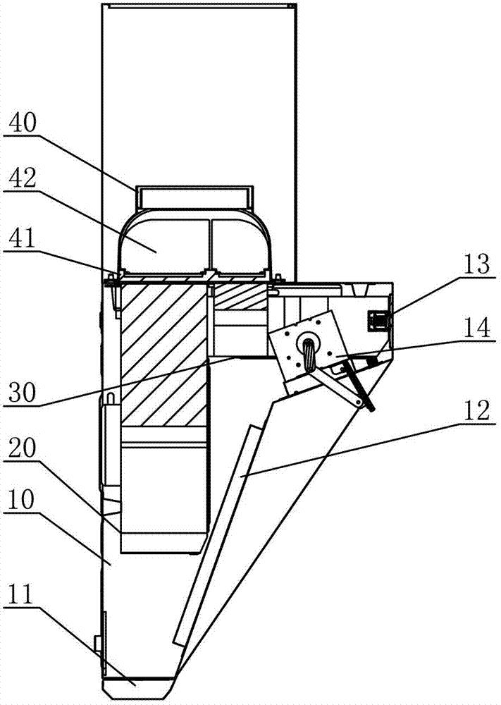
[0039] see Figure 1-Figure 12 , the range hood includes a hood main body 10 provided with a smoking port and a smoke exhaust port, the inner part of the hood main body 10 is provided with a first wind cabinet 20 for smoking at the side of the smoking port, and the inner top is provided with a hood for smoking The second wind cabinet 30 for smoking on the top of the mouth;

[0040] The first air cabinet 20 is composed of a group of fans, and the group of fans is provided with independent exhaust ends. The second air cabinet 30 is composed of two groups of fans, and the two groups of fans are respectively provided with independent exhaust ends.

[0041] see Figure 6-Figure 9 , the first wind cabinet 20 comprises a first volute 21 and a fan disposed therein, the fan comprises a first motor 22 and a first wind wheel 23 disposed in the first volute 21; the second wind cabinet 30 comprises The second volute 31 is composed of two groups of blowers arranged therein. The two groups...

no. 2 example

[0047] see Figure 13-Figure 16 , the main difference between this range hood and the first embodiment is that the first wind cabinet 20 includes the first volute 21 and two groups of fans arranged in it, and the two groups of fans include the first volute arranged in the first volute The first motor 22 and the first wind wheel 23 on both sides of the 21, the two exhaust ends arranged on the first volute 21 are close to the middle part, and the two groups of exhaust ends are respectively connected to the two exhaust ends on the rear side of the wind guide cover 40. The two sets of one-way exhaust passages are connected. Similarly, if one of the fans of the first wind cabinet 20 is turned on separately, it will not interfere with each other's exhaust ends, will not cause turbulence to reduce the smoking effect, and will not form an air flow. pour back. This range hood forms a three-dimensional or rectangular three-dimensional smoking on the cooktop through the combination of t...


PUM


Abstract

The invention discloses a range hood, which comprises a range hood main body provided with a smoke suction port and a smoke exhaust port and a control mechanism of the range hood main body, and is characterized in that a first air cabinet used for sucking smoke on the side of the smoke suction port is arranged on the inner side of the range hood main body, and a second air cabinet used for sucking smoke on the top of the smoke suction port is arranged on the inner top of the range hood main body, wherein the first air cabinet consists of a group of fans, and the group of fans are provided with independent air exhaust ends; or the first air cabinet consists of two groups of fans, and the two groups of fans are respectively provided with independent air exhaust ends; the second air cabinet consists of two groups of fans, and the two groups of fans are respectively provided with independent air exhaust ends; and the air exhaust ends of the first air cabinet and the second air cabinet are respectively communicated with the smoke exhaust port through one-way smoke exhaust channels. Three-dimensional smoke suction is formed on a kitchen range by combining top suction and side suction, the smoke suction effect is greatly improved, the oil smoke is prevented from running away to the greatest degree, and the defects of the product in the current market are overcome; and meanwhile, the range hood is simple in design, reasonable in structure, small in size and easy to mount.

Description

technical field [0001] The invention relates to a range hood. Background technique [0002] Range hoods on the market today are generally divided into two forms. [0003] The first is top suction. For example, Chinese Patent Document No. CN201615526U disclosed a range hood on October 27, 2010. The range hood includes a housing, and the front end of the housing is provided with a panel inclined forward. The panel The upper end is connected with a wind deflector through a hinge joint, and a support frame is provided on the panel corresponding to the lower end of the wind deflector, and a side air inlet gap is formed between the panel and the wind deflector. The upper end of the housing is provided with an outlet Air duct, the air outlet duct is provided with a wind wheel and a motor, an oil guide groove is provided in the housing, an oil guide pipe is provided at the lower end of the oil guide groove, and an oil collector is provided at the lower end of the outer housing. A...

Claims


Application Information

Patent Timeline
Patent Type & Authority Applications(China)
IPC IPC(8): F24C15/20
Inventor 谈启明
Owner 谈启明
Learn More