Staple bin assembly and stapler using same

A component and staple cartridge technology, applied in the direction of surgical fixation nails, etc., can solve the problems of affecting the surgical effect, increasing the pain of patients, and poor staple forming.

Active Publication Date: 2014-12-03
B J ZH F PANTHER MEDICAL EQUIP
View PDF6 Cites 0 Cited by
  • Summary
  • Abstract
  • Description
  • Claims
  • Application Information

AI Technical Summary

Problems solved by technology

[0003] The staple cartridge assembly of the tubular stapler currently used clinically, the suturing and cutting actions are performed simultaneously, and the cutting direction is the same as the staple output direction of the staple. The cutting knife must cut through the pad knife ring to complete the cutting action. This traditional anastomosis method of the staple cartridge assembly is likely to cause risks such as poor staple formation, staples falling to one side, and continuous tissue cutting, which increases the pain of the patient and affects the operation. Effect
[0004] It can be seen that there are obvious deficiencies and defects in the structure, method and use of tubular staplers in the prior art, and further improvement is urgently needed

Method used


Image

  • Staple bin assembly and stapler using same
  • Staple bin assembly and stapler using same
  • Staple bin assembly and stapler using same

Examples


Embodiment Construction

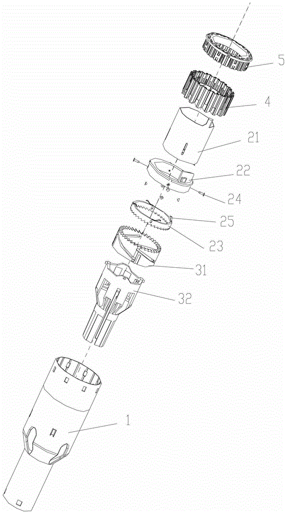
[0031] see Figure 1-3 As shown, a staple cartridge assembly of the present invention includes a staple cartridge cover 1, a staple cartridge 5 fixed on the upper end of the staple cartridge cover 1, a nail pusher 4 installed in the staple cartridge cover 1, a slit assembly and a driving assembly .

[0032] The following up, down, left and right are all based on figure 1 The orientation shown in is a standard description.

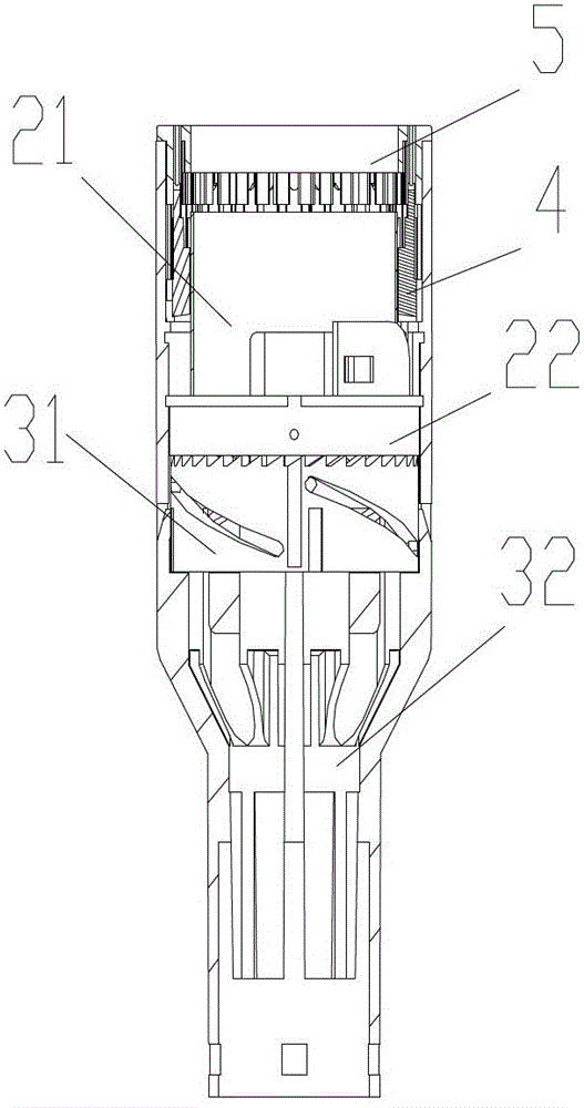
[0033] Among them, please refer to Figure 4 As shown, the kerf assembly includes a cutter slider 21 , a nail pusher slider 22 and a cutter gear ring 23 . The lower part of the cutter slider 21 is a cylinder, and the upper end is a cutting head 211. The push nail 4 and the push nail slider 22 can slide up and down and are set on the outside of the cylinder of the cutter slider 21. The push nail 4 is located on the push nail. Slider 22 above. The cutter gear ring 23 is installed on the bottom of the nail pushing slider 22 .

[0034] Please refer to F...


PUM


Abstract

The invention relates to a staple bin assembly and a stapler using the same. The staple bin assembly comprises a staple bin sleeve, a joint-cutting assembly, a driving assembly, a staple bin and a staple pushing plate, wherein the driving assembly comprises a driving seat and a driving gear; the driving seat can move in the staple bin sleeve in the up-down direction; a guiding column is arranged at the upper end of the driving seat; the driving gear is provided with a chute; the guiding column slides in the chute; the joint-cutting assembly comprises a cutter slider, a staple pushing slider and a cutter toothed ring; the lower part of the cutter slider is a barrel, and the upper end of the cutter slider is a cutting head; the staple pushing plate and the staple pushing slider can be slidably sleeved on the outer side of the barrel of the cutter slider in the up-down direction; the cutter toothed ring is arranged at the bottom of the staple pushing slider; and the lower end of the cutter toothed ring is meshed with the driving gear. A transmission assembly of the stapler can push the driving seat of the staple bin assembly under the action of a trigger. A stitching staple forming effect is good, tissues are cut smoothly, a surgical effect is good, the surgical efficiency is high, and the required triggering force is small; the staple bin assembly is safe and reliable; and the normal surgery can be guaranteed, so that the staple bin assembly and the stapler using the same are suitable to be popularized and used.

Description

technical field [0001] The invention relates to the field of medical instruments, in particular to a staple cartridge assembly and a stapler using the same. Background technique [0002] Stapler is a medical device that replaces traditional manual sutures in surgical operations. Among them, tubular staplers are widely used in human digestive tract operations, such as the ends of the esophagus, stomach, duodenum, and small intestine in the digestive tract or End-to-side anastomosis. Especially in the case where the operated interface site is relatively short or the field of vision is unclear, it is more necessary to use a stapler to close the wound. In surgical operations such as digestive tract reconstruction, the use of medical staplers to assist incision suture has the advantages of simple operation, rapid suturing, and basically no side effects and complications. Moreover, such devices can shorten operation time and improve operation efficiency. The specific method of u...

Claims


Application Information

Patent Timeline
Patent Type & Authority Patents(China)
IPC IPC(8): A61B17/115
CPCA61B17/1155
Inventor 李学军刘青
Owner B J ZH F PANTHER MEDICAL EQUIP
Why Eureka
Try Eureka