
Luminaire lifting device and liftable luminaire

A lifter and lift lamp technology, which is applied to lighting and heating equipment, lighting devices, lighting device components, etc., can solve problems such as insufficient light, inconvenient maintenance and replacement of lamps, inconvenient cleaning, and inability to adjust the position of lamps, etc., to achieve The effect of reliable power transmission

Inactive Publication Date: 2013-01-30
ZHEJIANG TENDENCY TECH
View PDF6 Cites 12 Cited by
  • Summary
  • Abstract
  • Description
  • Claims
  • Application Information

AI Technical Summary

Problems solved by technology

[0002] In factory sheds or hotel halls, the floors are generally relatively high, and it is inconvenient to maintain, replace and clean lamps and lanterns. It is often necessary to use high-power lamps for lighting. In places where centralized lighting is required, the light is often not sufficient.
At present, the position of the lamp cannot be adjusted, which cannot meet the needs of use in these occasions

Method used


Image

  • Luminaire lifting device and liftable luminaire
  • Luminaire lifting device and liftable luminaire
  • Luminaire lifting device and liftable luminaire

Examples


Embodiment Construction

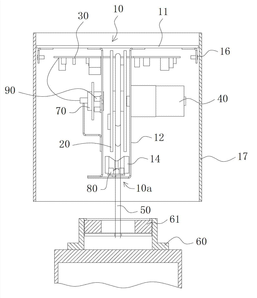
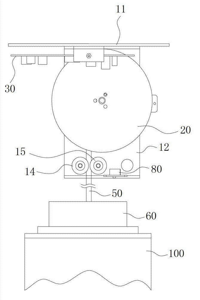
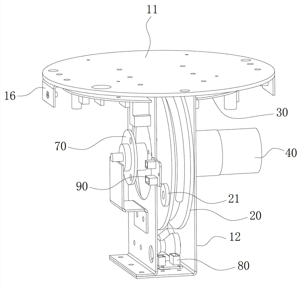
[0038] The embodiments of the present invention will be described in detail below with reference to the accompanying drawings, but the present invention can be implemented in many different ways defined and covered by the claims.

[0039] Figure 1 to Figure 3 shows a lamp lifter according to a first embodiment of the invention, with reference to Figure 1 to Figure 3 The lamp lifter includes a frame 10, a reel 20 supported on the frame 10, an electrical control panel 30, a motor 40 for driving the reel 20 to rotate, and a lamp wire 50 wound on the reel 20, And the lamp holder 60 suspended on the second end of the lamp wire 50 , wherein the first end of the lamp wire 50 located on the reel 20 is electrically connected to the slip ring 70 .

[0040] In the present invention, the lamp wire has the dual functions of conducting electricity and acting as a load-bearing load wire. The lamp 100 is installed on the lamp holder, and the winding wheel is driven by a motor. Stop, becau...


PUM


Abstract

The invention discloses a luminaire lifting device and a liftable luminaire. The luminaire lifting device comprises a machine frame, wire winding wheels and an electric control board supported on the machine frame, a motor used for driving the wire winding wheels to rotate, a lamp wire wound on the wire winding wheels, a sliding ring electrically connected with a first end of the lamp wire, and a lamp base arranged at a second end of the lamp wire in a hanging manner. In the invention, the lamp wire has double functions of electric conduction and load-bearing, the wire winding wheels are driven by the motor to realize lifting and suspension of the lamp base, and the functions of light and colour adjustment are realized, therefore the luminaire lifting device and the liftable luminaire can be suitable for the use on occasions requiring luminaire lifting or light and colour adjustment.

Description

technical field [0001] The invention relates to a lamp lifter and a lift lamp using the lamp lifter. Background technique [0002] In factory sheds or hotel halls, the floors are generally relatively high, and the maintenance, replacement and cleaning of lamps are very inconvenient. High-power lamps are often used for lighting. In places where centralized lighting is required, the light is often not sufficient. At present, the position of the lamp cannot be adjusted, which cannot meet the needs of use in these occasions. Contents of the invention [0003] The object of the present invention is to provide a lamp lifter and a lift lamp, which can be used in occasions that require lifting of lamps. [0004] For this reason, according to one aspect of the present invention, a lamp lifter is provided, including a frame, a reel supported on the frame, an electrical control board, a motor for driving the reel to rotate, and a The lamp wire on the lamp wire, the slip ring electr...

Claims


Application Information

Patent Timeline
IPC IPC(8): F21V21/36
Inventor 徐承东
Owner ZHEJIANG TENDENCY TECH
Learn More