Air handling equipment Water system

一种空气处理、设备的技术,应用在空气处理设备水系统领域,能够解决冷凝热没有得到有效利用、高品质的能源没有得到有效利用、设备初投资大等问题,达到结构简单、成本低廉、工作可靠的效果

Inactive Publication Date: 2016-12-21
刘雄
View PDF11 Cites 0 Cited by
  • Summary
  • Abstract
  • Description
  • Claims
  • Application Information

AI Technical Summary

Problems solved by technology

[0003] 1) In the process of producing chilled water, the condensation heat of refrigeration equipment is not effectively utilized, but is directly discharged into the environment; 2) Fuel oil and gas boilers are used to provide low-grade heat required for air reheating, high-quality The energy has not been effectively used; 3) The initial investment of equipment is relatively large

Method used


Image

  • Air handling equipment Water system
  • Air handling equipment Water system
  • Air handling equipment Water system

Examples


Embodiment 1

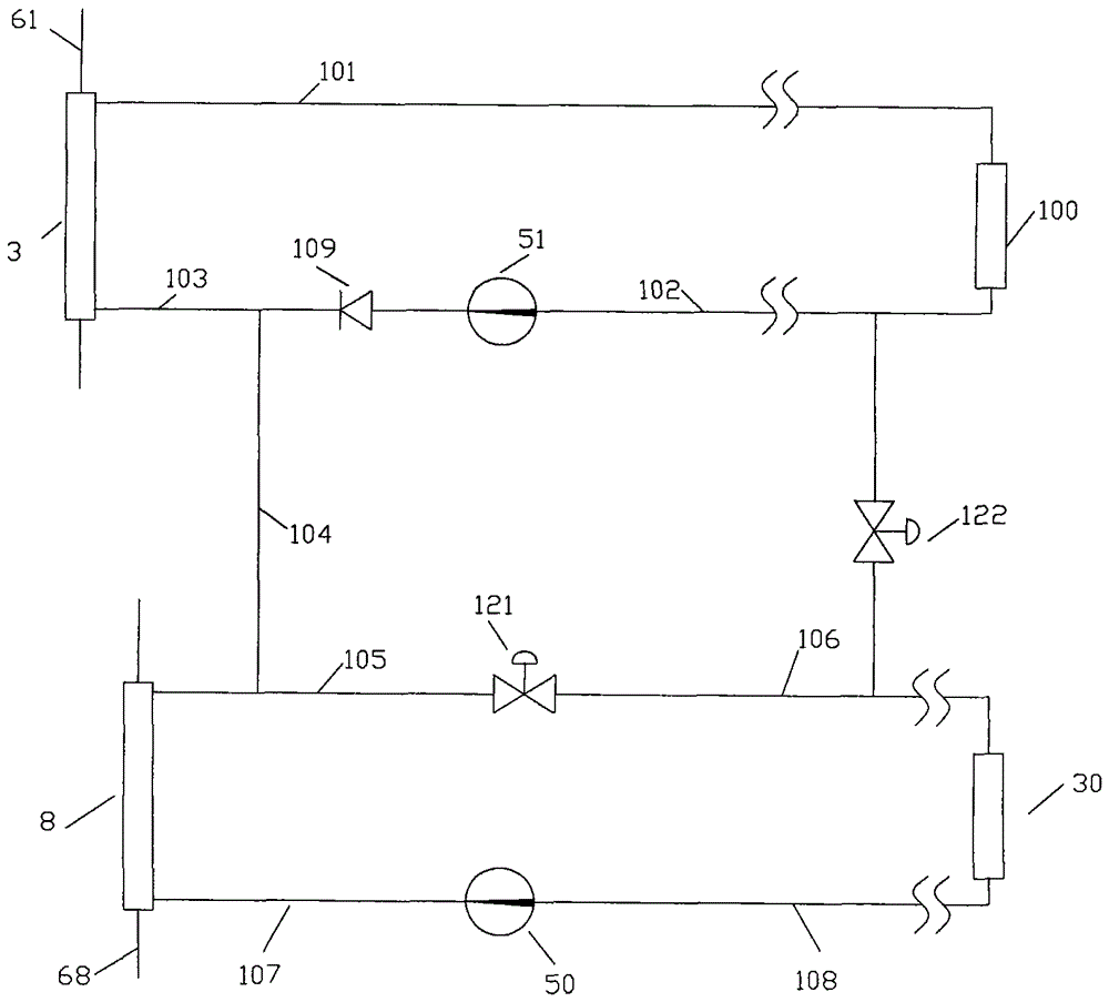
[0046] figure 2 The air treatment equipment water system shown includes the following components: user-side heat exchanger 3 of air-conditioning and refrigeration equipment, hot water heater 8 of air-conditioning and refrigeration equipment, reheater 30, hot water circulation pump 50, air-conditioning water circulation pump 51, Cooler 100 , check valve 109 , first water flow control valve 121 , second water flow control valve 122 .

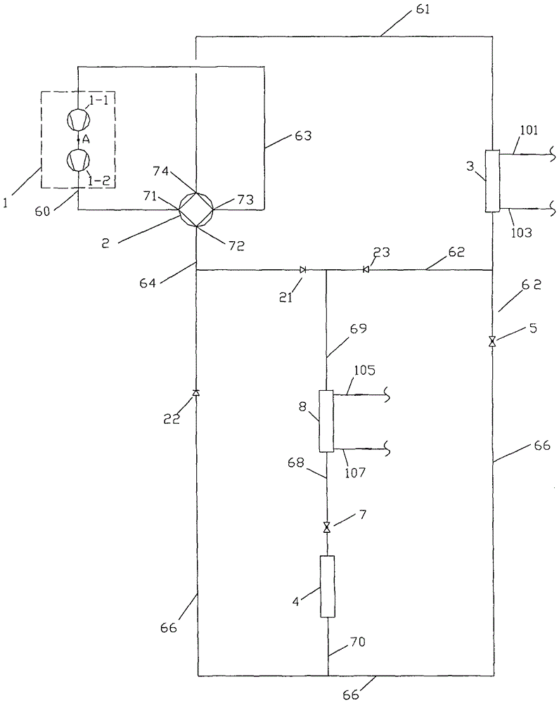
[0047] this invention figure 2 The water system of the air handling plant shown, and the cooling and heating system for it during operation figure 1 The air-conditioning and refrigeration equipment shown can realize the following functions during the year-round operation. When realizing each function, figure 1 Shown air-conditioning and refrigeration equipment, and the matching of this embodiment figure 2 The working process of the water system of the air handling equipment shown is as follows.

[0048] (1) Separate production of chilled wa...

Embodiment 2

[0107] like image 3 As shown, it is the same as Example 1 figure 2 The difference of shown air treatment equipment water system is: present embodiment image 3 The air handling equipment water system shown has a fifth water flow control valve 125 and a bypass regulating valve 130 added to its air conditioning water subsystem.

[0108] The fifth water flow control valve 125 and the bypass regulating valve 130 are in image 3 The connection scheme in the water system of the air treatment equipment shown is: one end of the fifth water flow control valve 125 is connected to the outlet end of the cooler 100, and the other end of the fifth water flow control valve 125 is connected to the inlet of the air-conditioning water circulation pump 51 through the one hundred and second pipe 102 The inlet port of the bypass regulating valve 130 is connected with the one hundred and first pipe 101 between the water side outlet port of the user-side heat exchanger 3 and the inlet port of th...

Embodiment 3

[0157] like Figure 5 As shown, it is the same as Example 1 figure 2 The difference of shown air treatment equipment water system is: present embodiment Figure 5 The air handling equipment water system shown has a three-way flow regulating valve 140 added to its air conditioning water subsystem.

[0158] The three-way flow regulating valve 140 is in Figure 5 The connection scheme of the water system of the air treatment equipment shown is: the direct connection point E of the three-way flow regulating valve 140 is connected to the outlet of the cooler 100, and the confluence connection point B of the three-way flow regulating valve 140 passes through the one hundred and second pipeline 102 It is connected to the inlet of the air-conditioning water circulation pump 51, and the bypass connection point F of the three-way flow regulating valve 140 is connected to the one hundred and first pipe 101 between the water side outlet of the user-side heat exchanger 3 and the inlet o...


PUM


Abstract

The invention discloses an air treatment equipment water system. The system comprises an air-conditioning water sub-system and a hot water sub-system, wherein the air-conditioning water sub-system comprises a user side heat exchanger of air-conditioning refrigeration equipment, an air-conditioning water circulating pump, a cooler of an air treatment unit and a check valve; the water side inlet end of the user side heat exchanger is connected with the water side outlet end of the user side heat exchanger sequentially through a 103rd pipeline, a check valve outlet end, a check valve inlet end, the outlet end of the air-conditioning water circulating pump, the inlet end of the air-conditioning water circulating pump, a 102nd pipeline, the outlet end of the air treatment unit cooler, the inlet end of the air treatment unit cooler and a 101st pipeline; and the hot water sub-system comprises a hot water heater of the air-conditioning refrigeration equipment, a reheater of the air treatment unit and a hot water circulating pump. The requirement for cold and heat quantities of the air treatment equipment water system can be simultaneously met by using one air-conditioning refrigeration equipment, and the air treatment equipment water system has a simple structure, reliable work and low cost.

Description

technical field [0001] The invention relates to an air treatment equipment water system, which belongs to the technical field of air conditioning. Background technique [0002] The air handling equipment in the central air-conditioning system generally includes at least a cooler and a reheater. The air to be treated is usually cooled and dehumidified through the cooler first, and then enters the reheater. After the air is heated to the supply air temperature, And then sent to the air-conditioned room. It can be seen that the air handling equipment of the central air-conditioning system has the demand for cooling capacity and heat at the same time in the process of processing air. At present, the cooling capacity of the air handling equipment of the conventional central air-conditioning system is generally provided by the chilled water produced by the refrigeration equipment. Provide (for example: chiller), its heat is generally provided by hot water produced by oil and gas ...

Claims


Application Information

Patent Timeline
Patent Type & Authority Patents(China)
IPC IPC(8): F24F5/00F24F12/00F24F11/02F24F3/00
Inventor 刘雄
Owner 刘雄
Why Eureka
Try Eureka