Suspension subframe

一种悬架系统、副车架的技术,应用在副车架领域,能够解决板材冲压工序数量增大、副车架重量增加、制造复杂等问题,达到扩展自由度、提高作业性、提高安全性的效果

Active Publication Date: 2013-01-30
YOROZU CORP
View PDF9 Cites 2 Cited by
  • Summary
  • Abstract
  • Description
  • Claims
  • Application Information

AI Technical Summary

Problems solved by technology

[0004] However, if such a large-area plate is used, when the material is obtained from the base material during manufacture, the material is likely to be wasted, which may cause disadvantages in terms of cost.
In addition, in order to make the subframe highly rigid, unevenness may be formed locally, and reinforcements may be provided inside the upper and lower fins, but in this case, the weight of the entire subframe will increase, and not preferred
In particular, if it is desired to ensure rigidity by forming unevenness on the sheet, the number of stamping steps on the sheet will increase, making the manufacturing complicated and disadvantageous in terms of cost.

Method used


Image

  • Suspension subframe
  • Suspension subframe
  • Suspension subframe

Examples


Embodiment Construction

[0026] Embodiments of the present invention will be described in detail below.

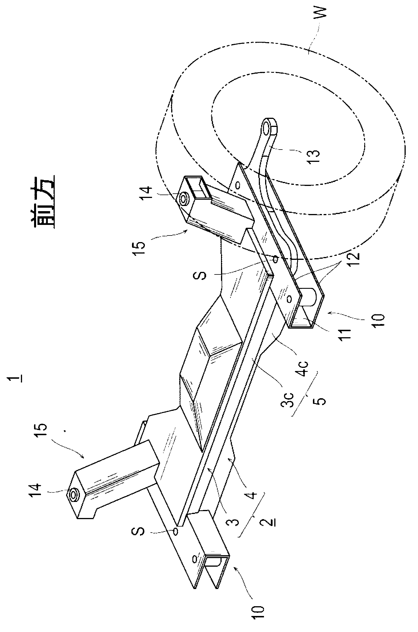
[0027] exist figure 1 Among them, the subframe 1 of the suspension system of this embodiment is used for the front suspension, and is roughly composed of a main body member 2 with a relatively large area that is arranged between two wheels (only one wheel is shown in the figure) W. It is composed of side end members 10 respectively attached to both side end portions of the main body member 2 in the vehicle width direction. The main body member 2 and the side end member 10 are attached to the vehicle body through the connecting member 15, but instead of using such a connecting member 15 having a predetermined height in the vertical direction, they may be attached to the side of the vehicle body directly or through a height adjusting member or the like. .

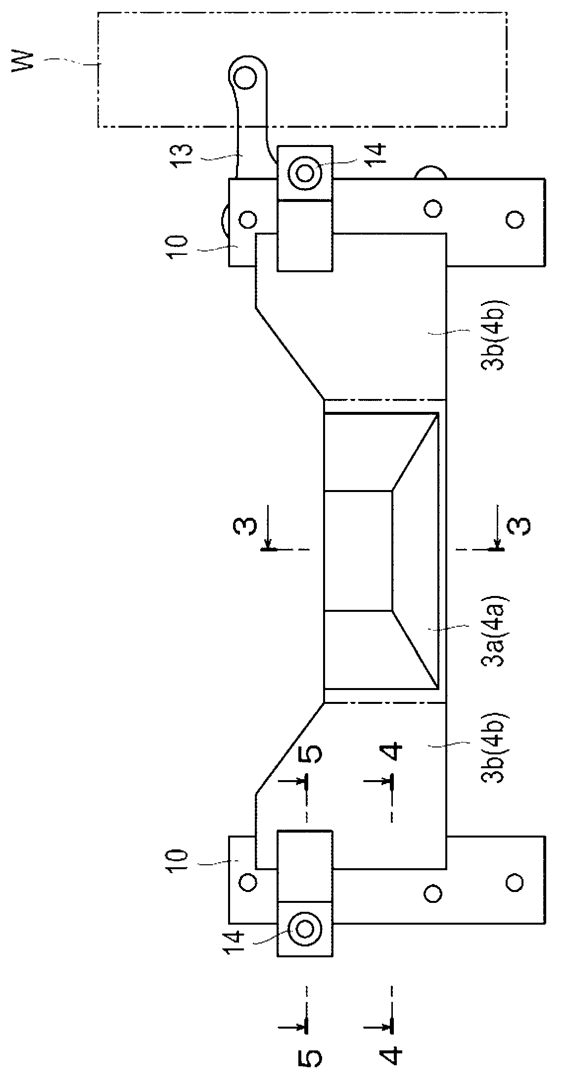
[0028] Further details are given below. First, if figure 1 , figure 2 As shown, the main body component 2 is substantially “I”-shaped in p...


PUM


Abstract

Disclosed is a suspension subframe (1) in which high rigidity side end members (10) are attached to both ends of a planar main member (2) so as to extend longitudinally to the vehicle. The suspension subframe (1) is light-weight and low-cost, does not result in waste in stock cutting, and has an extremely high rigidity against forces from front, back, left, right, etc., because of the side end members (10).

Description

technical field [0001] The invention relates to a subframe used in a suspension system of a motor vehicle. Background technique [0002] Generally, the suspension system of a vehicle has a subframe positioned between left and right wheels. The subframe is connected to the vehicle body side, and on the other hand, the subframe is also connected to wheels via a lower rocker arm and a knuckle. Therefore, it is preferable that the subframe has sufficient rigidity against forces transmitted from the wheel side, from the front, rear, left, and right directions, or up and down directions, and that such inputs can be efficiently transmitted and reliably supported. [0003] Conventional subframes have used press-formed members of a relatively large sheet. In order to provide high rigidity to the subframe, for example, in the structure disclosed in JP Patent No. 2963749, a part of the sheet is formed. Concavity and convexity are formed, and in the structure of JP-A-2005-138652, a re...

Claims


Application Information

Patent Timeline
Patent Type & Authority Applications(China)
IPC IPC(8): B62D21/00
CPCB62D21/00B62D21/11
Inventor 高桥宽小礒洋平
Owner YOROZU CORP
Why Eureka
Try Eureka