Dust collector

A vacuum cleaner and worm technology, applied in the field of cleaning electrical appliances, can solve the problems of many parts and components, complex structure, reducing the production efficiency and assembly efficiency of the vacuum cleaner, etc., and achieve the effect of simplifying the structure and realizing the interchangeability.

Inactive Publication Date: 2016-08-03
JIANGSU MIDEA CLEANING APPLIANCES
View PDF6 Cites 2 Cited by
  • Summary
  • Abstract
  • Description
  • Claims
  • Application Information

AI Technical Summary

Problems solved by technology

However, the vacuum cleaner in the related art has a straight-through structure with many parts and complex structure, which reduces the production efficiency and assembly efficiency of the vacuum cleaner and increases the production cost of the vacuum cleaner.

Method used


Image

  • Dust collector
  • Dust collector
  • Dust collector

Examples


Embodiment Construction

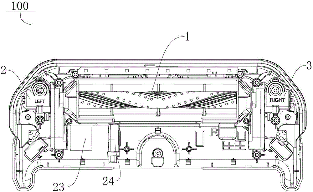
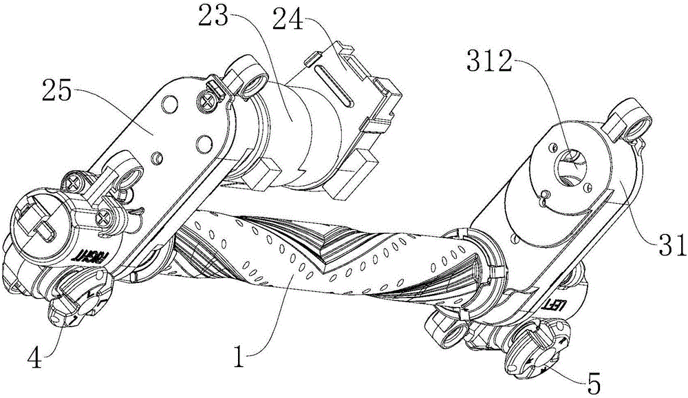
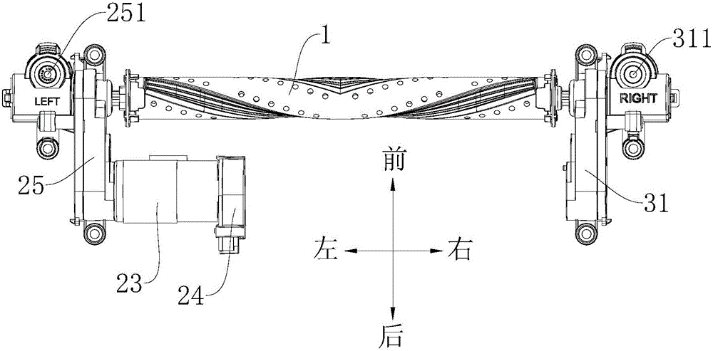
[0033] Refer below Figure 1-Figure 4 A vacuum cleaner 100 according to an embodiment of the present invention is described.

[0034] Such as figure 1 As shown, the vacuum cleaner 100 according to the embodiment of the present invention includes: a rolling brush 1 , a first transmission device 2 , a second transmission device 3 , a first side brush 4 and a second side brush 5 .

[0035] Specifically, the first transmission device 2 includes a first worm 21 and a first worm gear 22 meshed with each other, and the first worm 21 is connected to one end of the roller brush 1 (for example image 3 The left end of the roller brush 1 shown in); the second transmission device 3 includes a second worm and a second turbine meshed with each other, and the second worm connects the other end of the roller brush 1 (for example image 3 The right end of the rolling brush 1 shown in); the first side brush 4 is connected with the first turbine 22, and the second side brush 5 is connected wit...


PUM


Abstract

The invention discloses a vacuum cleaner, which comprises: a rolling brush, a first transmission device, a second transmission device, a first side brush and a second side brush, wherein the first transmission device includes a first worm and a first worm meshed with each other The first worm gear, the first worm is connected to one end of the rolling brush; the second transmission device includes a second worm and a second worm gear meshing with each other, the second worm is connected to the other end of the rolling brush; the first side brush is connected to the first worm gear, the second The two side brushes are connected with the second turbine, wherein at least one of the first worm and the second worm is connected with a driving device. According to the vacuum cleaner of the present invention, by arbitrarily installing the driving device on the left and right sides of the vacuum cleaner, and using the driving device to drive the roller brush, the first side brush and the second side brush to clean dust and garbage, the structure of the vacuum cleaner can be simplified and the vacuum cleaner can be realized. Interchange, common use and standardization of left and right parts.

Description

technical field [0001] The invention relates to the technical field of cleaning appliances, in particular to a vacuum cleaner. Background technique [0002] With the continuous development of the vacuum cleaner industry, people have higher and higher requirements for vacuum cleaners, and stricter requirements for the experience in use. However, the vacuum cleaner in the related art has a straight-through structure with many parts and complex structure, which reduces the production efficiency and assembly efficiency of the vacuum cleaner and increases the production cost of the vacuum cleaner. Contents of the invention [0003] The present invention aims to solve at least one of the technical problems existing in the prior art. Therefore, the present invention is to provide a vacuum cleaner that can achieve common use and standardization of components. [0004] The vacuum cleaner according to the present invention includes: a rolling brush; a first transmission device, th...

Claims


Application Information

Patent Timeline
IPC IPC(8): A47L9/00A47L9/04
CPCA47L9/00A47L9/0411A47L9/0433
Inventor 朴永哲
Owner JIANGSU MIDEA CLEANING APPLIANCES
Why Eureka
Try Eureka