
Upper yoke plate structure of magnetron of microwave oven

A technology of magnetron and microwave oven, applied in magnetron, discharge tube, transit time type electron tube, etc., can solve the problems of inconvenient disassembly and assembly, increase of production cost and technical requirements, etc.

Inactive Publication Date: 2010-06-23
LG ELECTRONICS (TIANJIN) APPLIANCES CO LTD
View PDF4 Cites 3 Cited by
  • Summary
  • Abstract
  • Description
  • Claims
  • Application Information

AI Technical Summary

Problems solved by technology

The assembly line is adjusted separately for different types of upper yoke plates, which also increases production costs and technical requirements
And now the assembly method of the upper yoke plate and the lower yoke plate uses the press-fit method, which leads to great inconvenience in disassembly and assembly in later inspection and maintenance

Method used


Image

  • Upper yoke plate structure of magnetron of microwave oven
  • Upper yoke plate structure of magnetron of microwave oven
  • Upper yoke plate structure of magnetron of microwave oven

Examples


Embodiment Construction

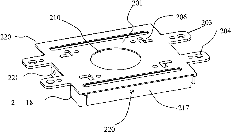
[0040] image 3 It is a schematic diagram of the upper yoke plate of the first embodiment of the present invention, and the upper yoke plate 220 shown can be installed on the lower yoke plate alternatively in the horizontal direction and in the vertical direction. from image 3 It can be seen that the two ends of the upper yoke plate 220 are symmetrically provided with four protruding pieces 203; each protruding piece 203 is provided with two mounting holes 204; The part outside 204 bends inward and extends along the direction perpendicular to the upper yoke plate 220 to form the first side baffle 218, wherein the first side baffle 218 is provided with a mounting hole 221; the upper yoke plate 220 The remaining two ends are bent inward and extend in a direction perpendicular to the upper yoke 220 to form a second side baffle 217 , and the second side baffle is provided with a mounting hole 220 . The installation hole 221 is located on the middle first baffle 218 , and the in...


PUM


Abstract

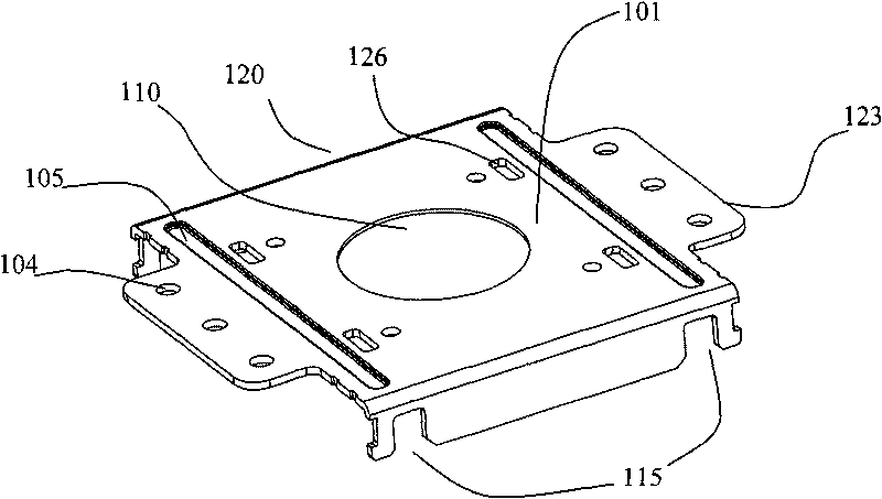
The invention discloses an upper yoke plate structure of a magnetron of a microwave oven, which comprises an upper yoke plate body and a projected sheet, wherein the center of the upper yoke plate is provided with a microwave energy output device installing hole, a hanging hole is arranged on the projected sheet, and the upper yoke plate is an upper yoke plate which can select two side edges to be combined with a lower yoke plate of the magnetron as required. Through the adoption of the upper yoke plate structure of the magnetron of the invention, the standard unionization of the magnetron can be realized, the confusion caused by human factors in the transportation process can be effectively reduced, and different models do not need to be distinguished again in the assembling process.

Description

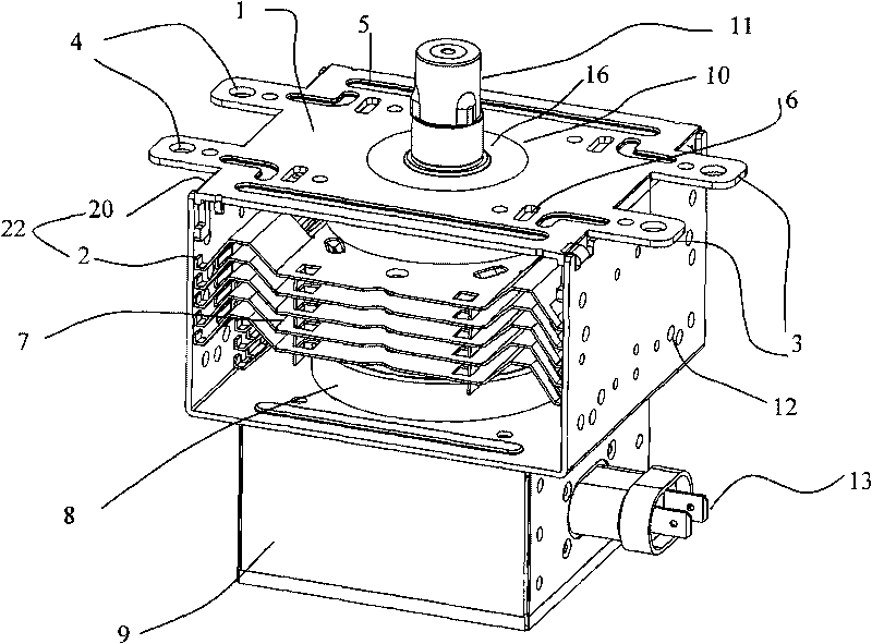
technical field [0001] The invention relates to an upper yoke plate structure of a microwave oven magnetron, in particular to a standardized upper yoke plate structure of a microwave oven magnetron. Background technique [0002] Generally speaking, a magnetron is an electronic device that can convert electrical energy into microwave electromagnetic energy, and is mainly used in microwave ovens or lighting appliances. figure 1 It is an oblique view of the components of the microwave oven magnetron in the prior art. This prior art magnetron includes a "mouth"-shaped yoke iron 22, which is formed by combining an upper yoke plate 20 and a lower yoke plate 2; the upper yoke plate 20 has four protruding ends 3, wherein the upper yoke plate 20 The main body 1 of the yoke plate is provided with a suspension hole 6, which is used to pre-position the magnetron when the magnetron is installed in the waveguide; the main body 1 of the upper yoke plate is also provided with a reinforcing...

Claims


Application Information

Patent Timeline
Patent Type & Authority Applications(China)
IPC IPC(8): H01J23/00H01J25/50
Inventor 郭长青
Owner LG ELECTRONICS (TIANJIN) APPLIANCES CO LTD
Learn More