Flange punching die

A technology for punching punches and hole dies, which is used in punching tools, metal processing equipment, manufacturing tools, etc., can solve problems such as difficulty in operation, reduce production efficiency, increase labor intensity, etc., achieve simple structure and assembly, improve production efficiency, and reduce labor. the effect of strength

Inactive Publication Date: 2013-02-06
DALIAN YILIAN METAL FORMING
View PDF0 Cites 6 Cited by
  • Summary
  • Abstract
  • Description
  • Claims
  • Application Information

AI Technical Summary

Problems solved by technology

[0002] In the prior art, the structure of the flange punching die is complicated, the service life is short, the operation is difficult during use, and accurate positioning cannot be performed, so the labor intensity is increased, the production efficiency is reduced, and the product quality is greatly affected

Method used


Image

  • Flange punching die
  • Flange punching die

Examples


Embodiment Construction

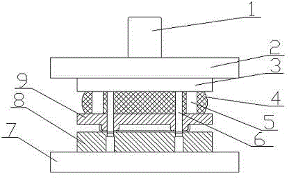
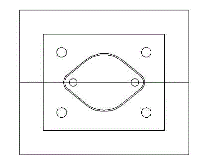
[0010] Such as figure 1 and figure 2 As shown, the flange punching die includes a die handle 1, an upper template 2, a fixed plate 3, a guide post 5, a punching punch 6, a lower template 7, a die 8 and a discharge plate 9, and the die handle 1 is installed on the upper template 2, the fixed plate 3 is installed under the upper template 2, the guide column 5 is installed between the fixed plate 3 and the unloading plate 9, the die 8 is installed on the lower template 7, the unloading plate 9 is installed on the die 8, punching The hole punch 6 is arranged between the fixed plate 3 and the lower template 7, and there are rubbers 4 on both sides of the guide post 5 between the fixed plate 3 and the unloading plate 9. The flange punching die of the present invention has a simple and accurate structure and assembly, and is easy to use. Long service life, convenient operation and accurate positioning during use, thus reducing labor intensity and improving production efficiency.


PUM


Abstract

The invention discloses a flange punching die which comprises a die shank (1), an upper die plate (2), a fixing plate (3), guide posts (5), male punching dies (6), a lower die plate (7), a female die (8) and a stripper plate (9). The die shank (1) is mounted on the upper die plate (2). The fixing plate (3) is mounted under the upper die plate (2). The guide posts (5) are mounted between the fixing plate (3) and the stripper plate (9). The female die (8) is mounted on the lower die plate (7). The stripper plate (9) is mounted on the female die (8). The male punching dies (6) are arranged between the fixing plate (3) and the lower die plate (7). The flange punching die is simple and precise in structure assembly and has a long service life. The flange punching die is convenient to operate and accurate in positioning in the use process; therefore, the labor intensity is reduced, and the production efficiency is improved.

Description

technical field [0001] The invention relates to a flange punching die. Background technique [0002] In the prior art, the flange punching die has a complex structure, short service life, difficult operation during use, and inaccurate positioning, thus increasing labor intensity, reducing production efficiency, and greatly affecting product quality. Contents of the invention [0003] The purpose of the present invention is to provide a flange punching die. [0004] The technical solution adopted by the present invention to achieve the above purpose is: a flange punching die, including a die handle (1), an upper template (2), a fixing plate (3), a guide post (5), a punching punch (6 ), the lower formwork (7), the die (8) and the stripper plate (9), the handle (1) is installed on the upper formwork (2), the fixed plate (3) is installed under the upper formwork (2), guide The column (5) is installed between the fixed plate (3) and the unloading plate (9), the die (8) is ins...

Claims


Application Information

Patent Timeline
Patent Type & Authority Applications(China)
IPC IPC(8): B21D28/34B21D37/12
Inventor 孙冬生范久卫
Owner DALIAN YILIAN METAL FORMING
Why Eureka
Try Eureka