Jet controller

A technology for jet regulators and housings, which is applied in the field of jet regulators and can solve problems such as the loss of sealing rings

Active Publication Date: 2013-02-06
NEOPERL
View PDF8 Cites 4 Cited by
  • Summary
  • Abstract
  • Description
  • Claims
  • Application Information

AI Technical Summary

Problems solved by technology

In such jet regulators, the necessary sealing ring would only entail th

Method used


Image

  • Jet controller
  • Jet controller

Examples


Embodiment Construction

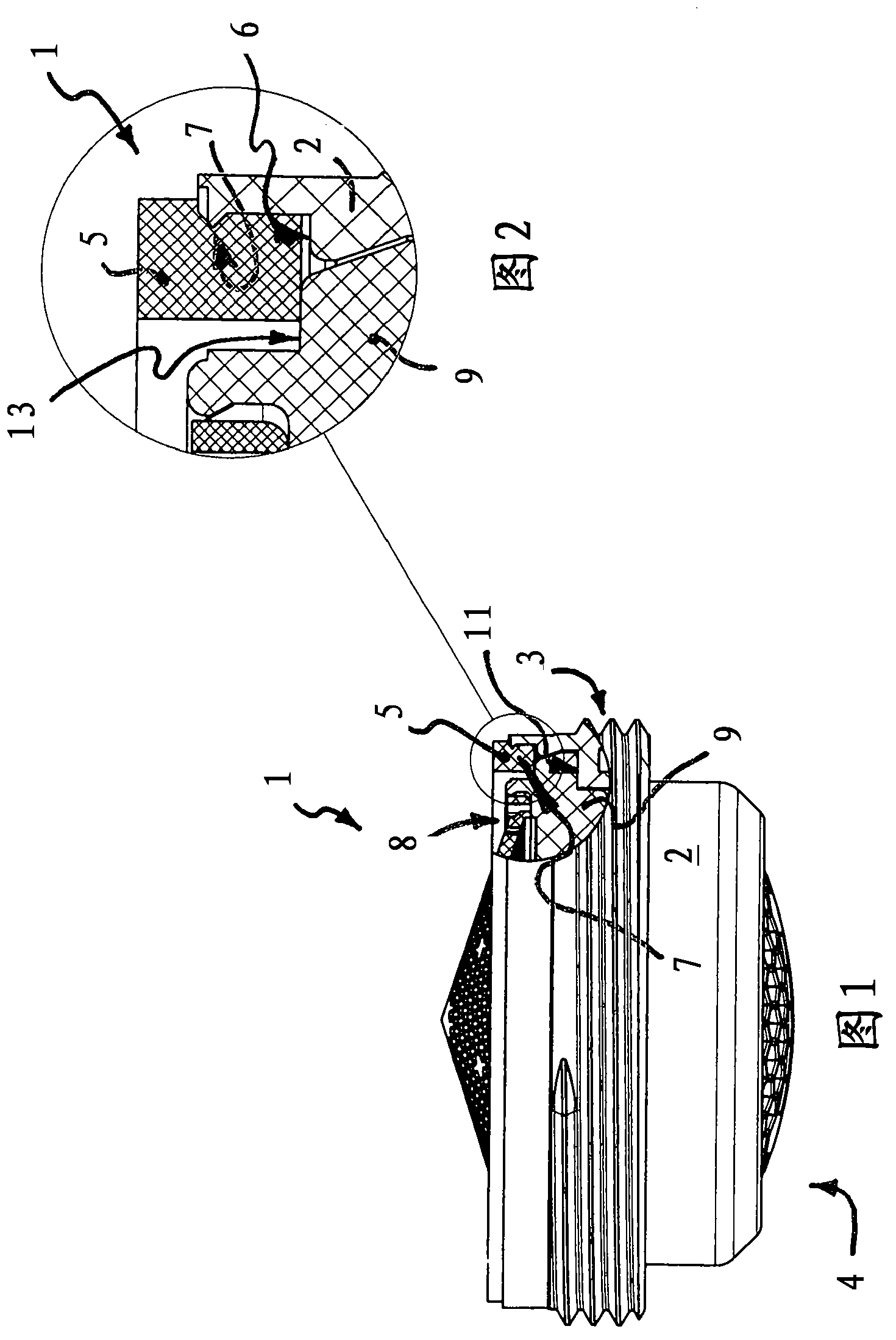
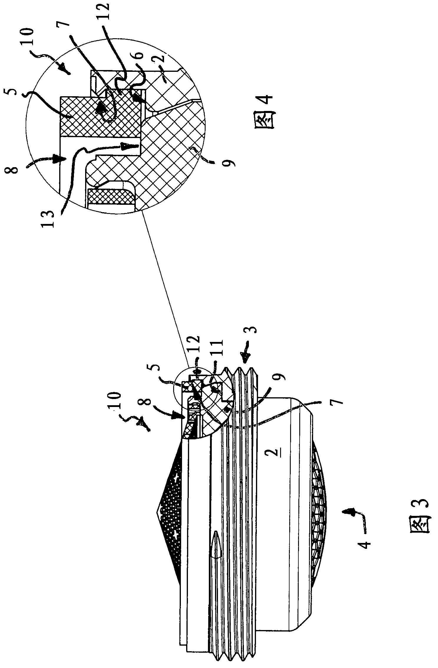
[0020] exist Figures 1 to 4 A jet regulator is shown in two embodiments 1, 10. The jet regulator embodiments 1, 10 shown here have a sleeve-shaped jet regulator housing 2, which can be fitted on the water outlet of a sanitary water valve not shown further here, so that there Creates a soft water jet that is uniform, non-splashing and, if necessary, foams. In order to be able to assemble the jet regulator housing 2 on the water outlet of the sanitary water valve, a sleeve-shaped outflow part can be provided, into which the jet regulator housing can be inserted from the inflow side up to an engagement stop part, wherein, the outflow outlet component has an external thread or an internal thread, and the external thread or internal thread cooperates with the matching thread at the water outlet.

[0021] However, preferred are the jet regulator embodiments 1, 10 shown here, in which the jet regulator housing 2 has an external thread 3 on its housing periphery, which can be screw...


PUM


Abstract

The invention relates to a jet controller (1) with a sleeve-shaped jet controller housing (2), which (2) can be mounted on the water outlet of a plumbing outlet fixture, and with a seal ring (5) made of elastic material, which (5) seals in the axial direction against an adjoining annular flange at the water outlet of the outlet fixture. On the front inner peripheral area (6) of the jet controller housing (2) on the inflow side, provided is at least one housing undercut (7), which (7) secures, on the jet controller housing (2), the seal ring (5), inserted into the housing interior (8) of the jet controller housing (2). In the jet controller (1) according to the invention, the seal ring (5) is effectively secured against unintended loss during transport or storage, for example.

Description

technical field [0001] The invention relates to a jet regulator, which comprises a sleeve-shaped jet regulator casing, which can be assembled on the water outlet of a sanitary water valve, and the jet regulator consists of an elastic The sealing ring is made of material, and the sealing ring is sealed in the axial direction relative to the adjacent annular surface on the water outlet of the water valve. Background technique [0002] A jet regulator is known from EP 1 770 225 B1, which is intended to form a uniform, non-splashing and softly foaming water jet at the water outlet of a sanitary water valve. The known jet regulator has a sleeve-shaped jet regulator housing, the jet-shaping functional element being arranged in the housing interior of the jet regulator housing. The known jet regulator is associated with a sleeve-shaped spout part, into which the jet regulator housing can engage from the inflow side up to the stop. The outlet part has an internal thread, and the i...

Claims


Application Information

Patent Timeline
IPC IPC(8): E03C1/086
CPCE03C1/086B05B1/02B05B1/14B05B1/22E03C1/084
Inventor G·布卢姆
Owner NEOPERL
Why Eureka
Try Eureka