
Hydraulic system and its power distribution method and power distribution device

A technology of hydraulic system and distribution method, which is applied in the direction of machine/engine, mechanical equipment, engine control, etc., can solve the problem of engine stalling and other problems, and achieve the effect of excellent work efficiency and low fuel consumption

Active Publication Date: 2016-08-03
ZOOMLION HEAVY IND CO LTD
View PDF4 Cites 0 Cited by
  • Summary
  • Abstract
  • Description
  • Claims
  • Application Information

AI Technical Summary

Problems solved by technology

[0005] The present invention aims to provide a hydraulic system and its power distribution method and power distribution device to solve the problem in the prior art that the sum of the power of all hydraulic pumps may exceed the maximum output power of the engine and cause the engine to stall

Method used


Image

  • Hydraulic system and its power distribution method and power distribution device
  • Hydraulic system and its power distribution method and power distribution device
  • Hydraulic system and its power distribution method and power distribution device

Examples


Embodiment Construction

[0026] It should be noted that, in the case of no conflict, the embodiments in the present application and the features in the embodiments can be combined with each other. The present invention will be described in detail below with reference to the accompanying drawings and examples.

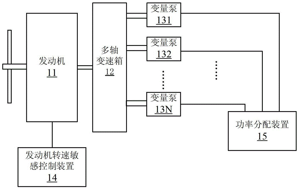
[0027] An embodiment of the present invention provides a hydraulic system, figure 1 is a schematic diagram of a hydraulic system according to an embodiment of the present invention, such as figure 1 As shown, the hydraulic system includes an engine 11, multiple variable pumps and a multi-shaft gearbox 12, wherein the multiple variable pumps are driven by the engine 11, and the multi-shaft gearbox 12 is used to respectively connect the engine 11 and the multiple variable pumps, except In addition to the above components, the hydraulic system of the embodiment of the present invention is also added: an engine speed sensitive control device 14, which is used to obtain the target speed and actual ...


PUM


Abstract

The invention provides a hydraulic system, as well as a power distribution method and a power distribution device thereof. The power distribution method of the hydraulic system includes steps as follows: acquiring a target rotating speed and an actual rotating speed of an engine; performing the rotating speed sensitivity control on the engine according to the deviation between the target rotating speed and the actual rotating speed, and stabilizing the rotating speed of the engine at the target rotating speed; and according to a preset distribution scheme, distributing the target output power corresponding to the target rotating speed to a plurality of variable capacity pumps. After the technical scheme provided by the invention is applied, the hydraulic system ensures that the engine operates at an optimal operation point through the rotating speed sensitivity control according to the operation environment of the engine, avoids the phenomenon of rapid rotating speed decrease, and distributes the optimal output power of the engine to the variable capacity pumps according to the preset distribution scheme, so as to achieve the optimal operation efficiency and the characteristic of low oil consumption under the condition of ensuring the normal operation of the hydraulic system.

Description

technical field [0001] The invention relates to the field of engineering machinery, in particular to a hydraulic system, a power distribution method and a power distribution device thereof. Background technique [0002] In the hydraulic system, the engine is the main power source, and the power distribution device distributes the output power of the engine to each hydraulic device, and the hydraulic device drives the action actuator. For construction machinery such as large hydraulic excavators with multiple pumps and multiple valves, the engine needs to supply power to multiple hydraulic systems such as the slewing system, cooling system, and pilot system at the same time. The power of the hydraulic system is equal to the product of the pressure of the hydraulic system and the flow rate of the hydraulic oil in the system. The pressure of the hydraulic system is determined by the load. The hydraulic oil is supplied by the hydraulic pump, and its flow rate is equal to the pro...

Claims


Application Information

Patent Timeline
Patent Type & Authority Patents(China)
IPC IPC(8): F02D29/04
Inventor 徐茂林单晓宁肖波王科
Owner ZOOMLION HEAVY IND CO LTD
Learn More