Visual location welding system and method based on robot welding

A robot welding and visual positioning technology, applied in the field of three-dimensional visual positioning system, can solve problems such as poor accuracy

Active Publication Date: 2020-12-25
XIAN CHISHINE OPTOELECTRONICS TECH CO LTD
View PDF5 Cites 19 Cited by
  • Summary
  • Abstract
  • Description
  • Claims
  • Application Information

AI Technical Summary

Problems solved by technology

The invention can visually locate the crossed steel bars, overcome the problem of poor precision of workpieces and fixtures, realize flexible and precise welding, and ensure welding quality; the invention realizes automatic calculation of weldi

Method used


Image

  • Visual location welding system and method based on robot welding
  • Visual location welding system and method based on robot welding
  • Visual location welding system and method based on robot welding

Examples


Embodiment Construction

[0060] The following will clearly and completely describe the technical solutions in the embodiments of the present invention with reference to the accompanying drawings in the embodiments of the present invention. Obviously, the described embodiments are only some, not all, embodiments of the present invention. Based on the embodiments of the present invention, all other embodiments obtained by persons of ordinary skill in the art without making creative efforts belong to the protection scope of the present invention.

[0061] 1. System composition and installation

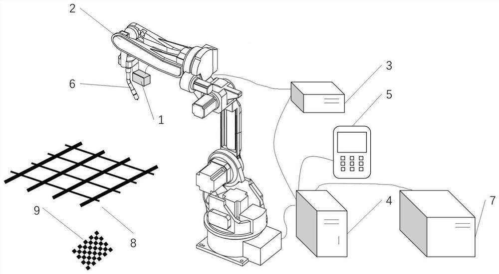
[0062] refer to figure 1 , a visual positioning welding system based on robot welding includes a visual scanning system 1, a three-dimensional camera 2, a robot 3, an industrial computer 4, a robot controller 5, a teaching device 6, a welding torch; 7, a welding machine; 8, a cross steel workpiece ; 9. Calibration board.

[0063] figure 1 It is an overall structural diagram of a visual positioning welding syst...


PUM


Abstract

The invention provides a visual location welding system and method based on robot welding. The visual location welding system is composed of a hand-eye calibration module, a photographing point location recording module and a welding execution module. The hand-eye calibration module is used for calculating a position and pose conversion relationship between a camera coordinate system and a robot coordinate system; three-dimensional information of crossed steel bars is acquired through the photographing point location recording module, and welding paths of the crossed steel bars are calculatedthrough a steel bar point cloud welding line extraction algorithm; and the welding paths are sent to the welding execution module, and the welding operation of steel bar crossing points is completed through the welding execution module . Through visual location of the crossed steel bars, the problem of poor precision of a workpiece and a clamp is solved, flexible and accurate welding is achieved,and the welding quality is guaranteed. According to the welding system, automatic calculation of the welding paths is achieved, and the demonstration of the welding paths is omitted; the robot demonstration process is simplified, and the requirement for operators is reduced; and the welding automation of the steel bars is achieved, and the welding effect and the production efficiency are improved.

Description

technical field [0001] The invention belongs to the technical field of three-dimensional visual positioning systems, and relates to a visual positioning welding system and a welding method based on robot welding paths. Background technique [0002] With the development of society and the extensive development of infrastructure construction, structural parts such as steel cages and steel mesh are widely used, but at present they are usually welded manually. First, the steel bars are positioned on the tooling and welded into mesh units. The position is a cross node, but in the actual welding process, due to the influence of human factors and workpiece deviation, the welding quality of the solder joints is inconsistent, making the welding quality unstable, resulting in uneven quality of the steel mesh processed by different welders. impact on subsequent processes. In addition, the cost of manual welding is constantly increasing, and the welding speed is slow and the constructi...

Claims


Application Information

Patent Timeline
IPC IPC(8): B23K37/02B23K37/00
CPCB23K37/0252B23K37/00
Inventor 雷浩姜军伟李晓晓彭磊马力李欢欢杨涛周翔
Owner XIAN CHISHINE OPTOELECTRONICS TECH CO LTD
Why Eureka
Try Eureka