Inter-shaft permanent magnetic coupling mechanism

A permanent magnet coupling, shaft-to-shaft technology, applied in electromechanical devices, electromechanical transmission devices, electrical components, etc., can solve the problems of shortened equipment life, poor stability of electronic devices, vibration, etc., to reduce equipment accuracy requirements and installation. Difficulty, realization of soft-start function, effect of large misalignment

Active Publication Date: 2015-11-18
JIANGSU MAGNET VALLEY TECH
View PDF6 Cites 0 Cited by
  • Summary
  • Abstract
  • Description
  • Claims
  • Application Information

AI Technical Summary

Problems solved by technology

Due to the complex and changeable operation of the system, it is difficult to accurately ensure the alignment of the two axes, and the equipment will vibrate after a period of operation, thereby accelerating wear and shortening the life of the equipment
[0004] 2. At present, frequency conversion and speed regulation are widely used in industrial sites. The output speed is controlled by controlling the motor. The price is relatively expensive, and the structure and operation are complicated. The power electronic devices of the frequency converter work in the switch state, thus generating a large number of harmonics and polluting the power grid. Affects communication, and the stability of electronic devices is not good, it is easy to age, the service life is not long, and the requirements for the environment are high, and there are great requirements for the ambient temperature, humidity and dust, so it is not suitable for working in harsh environments
In this type of coupler with existing structures, the direction of the magnetic field in the permanent magnets distributed along the circumference is usually perpendicular to the magnetic field action surface between the conductor rotor and the permanent magnet rotor, and the magnetic field distribution is scattered and the intensity is not high (the highest magnetic induction The strength can only reach 400~500mT), if you want to transmit a large torque, you need to make the structure larger, which limits the promotion of this technology

Method used


Image

  • Inter-shaft permanent magnetic coupling mechanism
  • Inter-shaft permanent magnetic coupling mechanism

Examples


Embodiment Construction

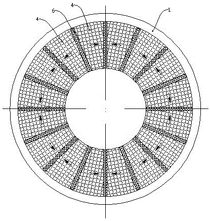
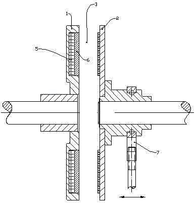
[0012] As shown in the figure, the inter-shaft permanent magnetic coupling mechanism of the present invention includes a coaxially arranged permanent magnet rotor 1 and a conductor rotor 2. Permanent magnets and conductors are respectively distributed on the permanent magnet rotor 1 and the conductor rotor 2. The permanent magnet rotor 1 Both the conductor rotor 2 and the conductor rotor have a disc structure, and the end faces of the permanent magnet rotor 1 and the conductor rotor 2 face each other to form an air gap 3; the permanent magnet on the permanent magnet rotor 1 includes a main magnet 4 and an auxiliary magnet 5; a plurality of main magnets 4 Distributed along the circumference, a magnetizer 6 made of a magnetizer is arranged between adjacent main magnets 4; the auxiliary magnet 5 is located on the side of each magnetizer 6 away from the conductor rotor 2; the main magnet 4 The magnetic pole direction of the magnetic pole (that is, the direction of the connection be...


PUM


Abstract

The invention relates to an inter-shaft permanent magnet coupling mechanism used for transmitting torque between two rotating shafts. The mechanism is characterized in that a permanent magnet rotor and a conductor rotor are of disk structures, and the end faces of the permanent magnet rotor and the conductor rotor are opposite and form an air gap; a plurality of main magnets on the permanent magnet rotor are distributed along the circumference, magnetizers made of permeability magnetic materials are put between adjacent main magnets, and auxiliary magnets are arranged on the sides, far from the conductor rotor, of the magnetizers; the magnetic pole directions of the main magnets are positioned on the circumferential direction of the permanent magnet rotor, and the magnetic pole directions of adjacent main magnets are opposite or reverse; the magnetic pole directions of the auxiliary magnets are vertical to the end face of the permanent magnet rotor, and the magnetic pole directions of adjacent auxiliary magnets are opposite; and the magnetic poles on the sides on which two adjacent main magnets and one auxiliary magnet are in contact with the same magnetizer have the same polarity. The mechanism can transmit larger torque, can adjust the transmitted torque, has compact structure and low requirement for installation precision, and is stable in transmission and adjustment.

Description

technical field [0001] The invention relates to a mechanism transmission device, in particular to an inter-shaft permanent magnetic coupling mechanism for torque transmission between two rotating shafts. Background technique [0002] For torque output and adjustment, there are many ways in the prior art, including: [0003] 1. Coupling mechanisms widely used in industry at present, these mechanisms are mostly rigid or hydraulic coupling connections, and the transmission torque and speed cannot be adjusted. Due to the complex and changeable operating conditions of the system, it is difficult to accurately ensure the alignment of the two axes. After a period of operation, the equipment will vibrate, which will accelerate wear and shorten the life of the equipment. [0004] 2. At present, frequency conversion and speed regulation are widely used in industrial sites. The output speed is controlled by controlling the motor. The price is relatively expensive, and the structure an...

Claims


Application Information

Patent Timeline
Patent Type & Authority Patents(China)
IPC IPC(8): H02K51/00
Inventor 徐俊峰
Owner JIANGSU MAGNET VALLEY TECH
Why Eureka
Try Eureka