

LED lamp adjustable in luminance and color temperature
A technology of LED lamps and LED light-emitting tubes, applied in the field of lighting, can solve the problems of high production cost and failure rate, and achieve the effects of reducing production cost and failure rate, reducing occupation, and simplifying circuits
- Summary
- Abstract
- Description
- Claims
- Application Information
AI Technical Summary
Benefits of technology
Problems solved by technology
Method used
Image

Examples
Embodiment 1
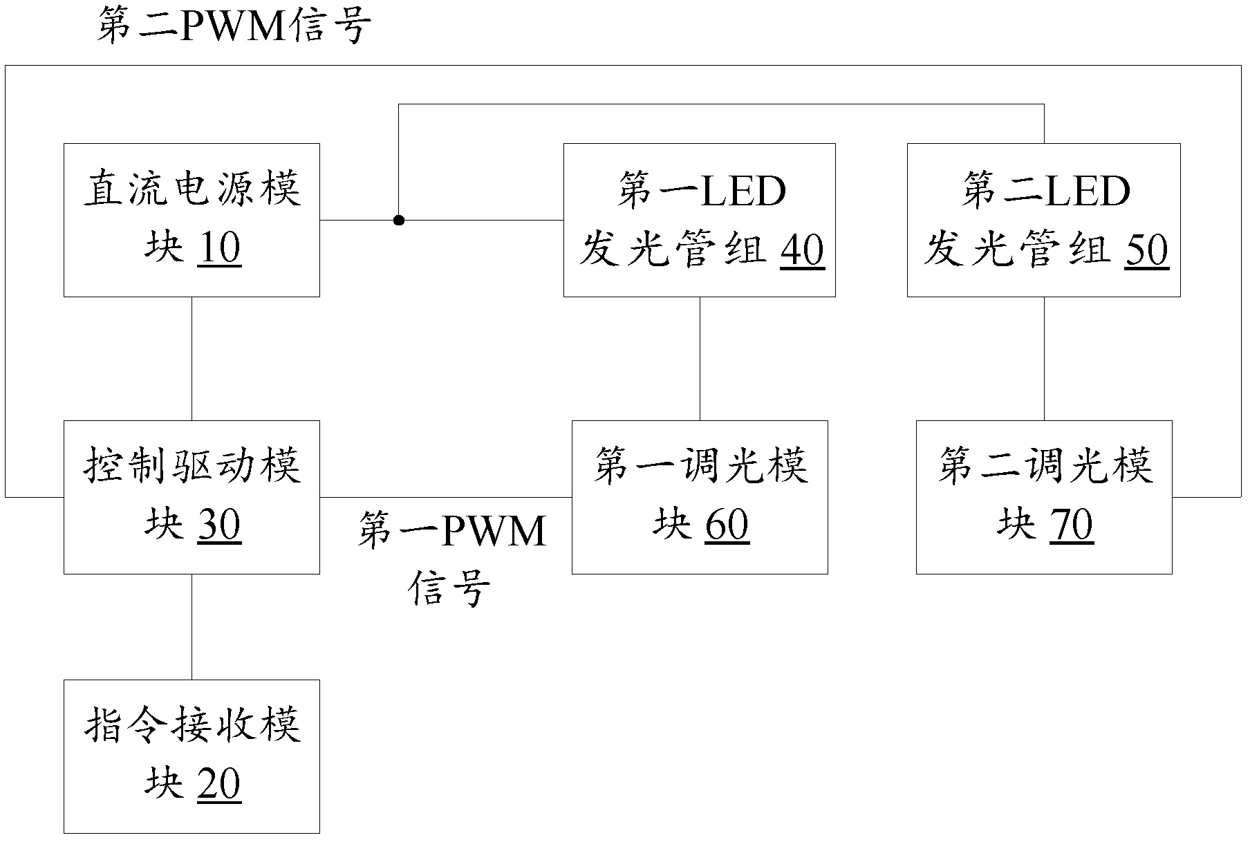
[0017] figure 1 A schematic diagram showing an LED lamp with adjustable brightness and color temperature according to Embodiment 1 of the present invention, as shown in figure 1 As shown, the LED lamp includes: a DC power supply module 10, an instruction receiving module 20, a control drive module 30, a first LED light-emitting tube group 40, a second LED light-emitting tube group 50, a first dimming module 60 and a second dimming module Module 70, the connections and functions of each module are as follows:
[0018] The DC power supply module 10 is used to provide working voltage for the control drive module 30, the first LED light-emitting tube group 40 and the second LED light-emitting tube group 50;
[0019] The instruction receiving module 20 is configured to receive control instructions, for example, the control instructions issued by the user by operating the remote control or by other means, which are not limited in the embodiments of the present invention;
[0020] ...
Embodiment 2
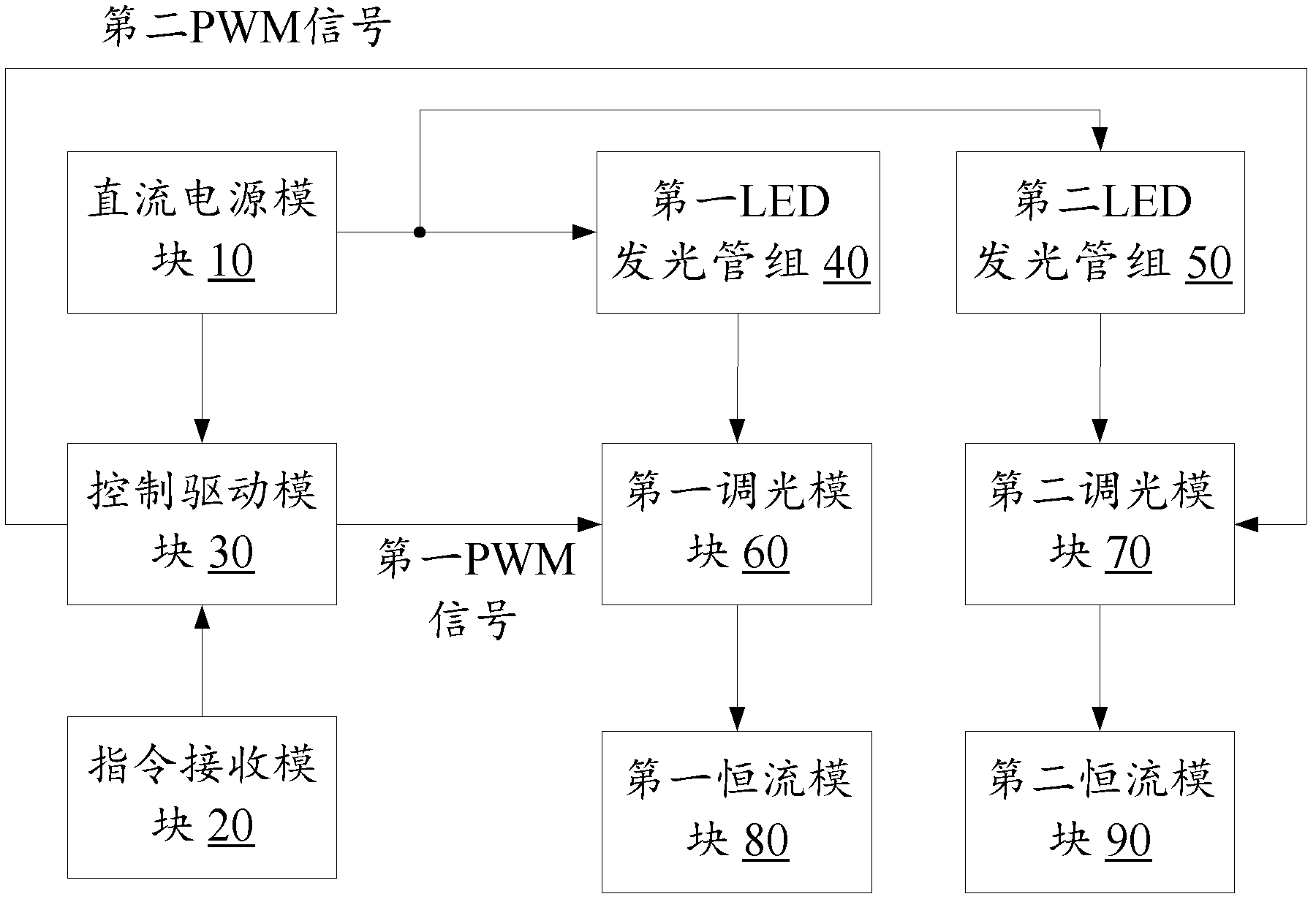
[0026] like figure 2 As shown, in order to ensure that the LEDs in the two groups of LED light-emitting tubes can work in the best state when the LEDs are turned on, the second embodiment of the present invention adds two constant current modules to the LED lamps: the first constant current module 80 and the first constant current module 80. The second constant current module 90 realizes power supply for two groups of LED light-emitting tube groups in a linear constant current manner.
[0027] like figure 2 As shown, the first constant current module 80 is connected to the first dimming module 60, and the first constant current module 80 is used to flow through the first LED light emitting tube group 40 when the first LED light emitting tube group 40 is working (that is, conducting). The current value of the LEDs in the group 40 is maintained as the rated operating current value of the LEDs in the first LED light-emitting tube group 40; and the second constant current modul...
Embodiment 3
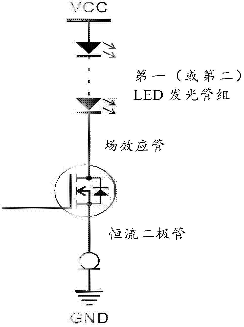
[0031] image 3 A circuit diagram of the first (or second) LED light-emitting tube group, the first (or second) dimming module and the first (or second) constant current module in the LED lamp according to the third embodiment of the present invention is shown. like image 3 As shown, in the third embodiment, any one of the LED light-emitting tube groups in the first and second embodiments can be composed of one or more LEDs connected in series in the forward direction, and any dimming module can be realized by using a field effect tube. , any one of the constant current modules in the second embodiment can be realized by using a constant current diode, and the constant current value of the constant current diode is equal to the rated operating current value of the LED.
[0032] like image 3 As shown, in the first LED light-emitting tube group or the second LED light-emitting tube group, multiple LEDs are connected in series in the forward direction, wherein the series in t...
PUM
 Abstract
Description
Claims
Application Information