Cable detecting equipment

A detection equipment and cable technology, which is applied in the field of cable detection equipment, can solve problems such as inconstant cone angle, limited cone detection rotation angle and speed, and unstable weights, so as to improve accuracy and avoid load swinging Effect

Active Publication Date: 2013-02-13
HONGDU TESTING EQUIP
View PDF6 Cites 12 Cited by
  • Summary
  • Abstract
  • Description
  • Claims
  • Application Information

AI Technical Summary

Problems solved by technology

[0004] However, the above-mentioned existing cable detection equipment has the following defects when testing the conical bending resistance of the cable: 1. According to the relevant testing standards, when doing the cone detection, the cable needs to be subjected to a constant tension in the direction of the predetermined angle, and In the actual testing process, in addition to gravity and cable tension, the weight of the pulling cable is also subjected to the centrifugal force generated during rotation, which cause

Method used


Image

  • Cable detecting equipment
  • Cable detecting equipment
  • Cable detecting equipment

Examples


Embodiment Construction

[0027] It should be noted that, in the case of no conflict, the embodiments in the present application and the technical features in the embodiments can be combined with each other. The present invention will be further described in detail below in conjunction with the drawings and specific embodiments.

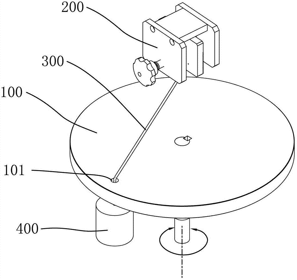
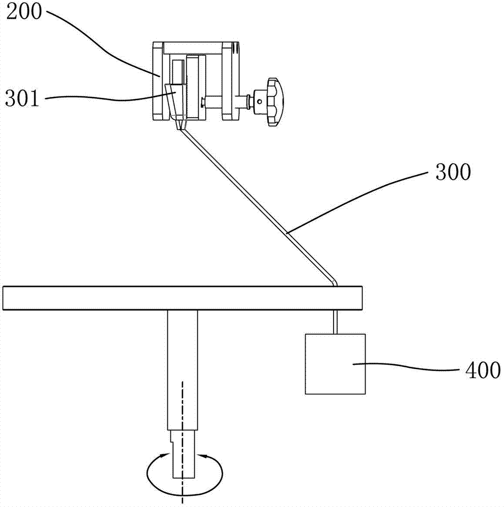
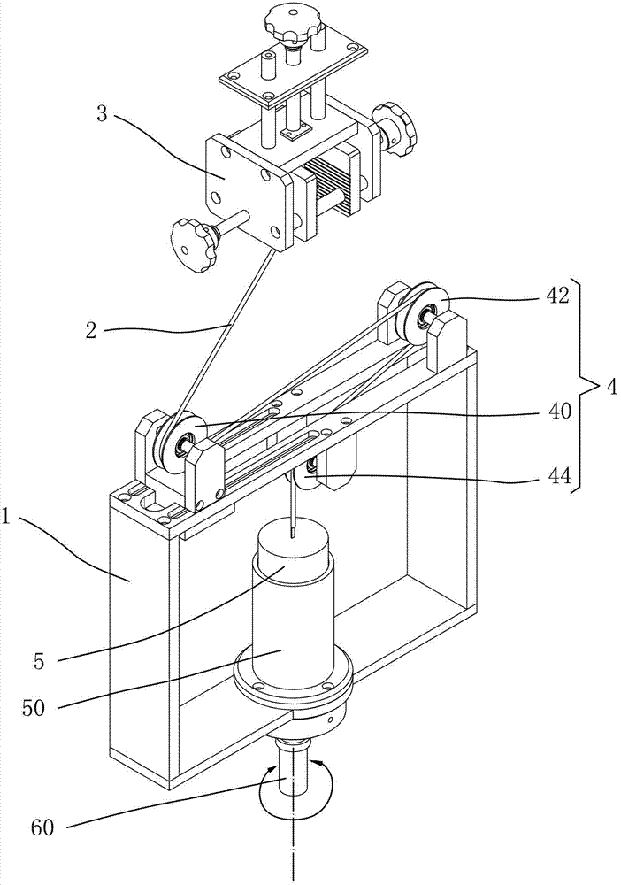
[0028] Such as image 3 and Figure 4 As shown, the present invention provides a cable detection device, including a rotating bracket 1, a clamp 3 located directly above the center of the rotating bracket 1 for clamping the first end of the cable 2 to be tested, and arranged on the rotating bracket 1 to be tested. The guide mechanism 4 for positioning and guiding the cable 2, the load 5 for pulling and tightening the cable 2 to be tested, and the driving mechanism for driving the rotating bracket 1 to rotate around the center of rotation.

[0029] in such as image 3 and Figure 4 In the shown embodiment, the rotating bracket 1 is generally in the shape of a rectangular fr...


PUM


Abstract

The invention relates to cable detecting equipment. The cable detecting equipment comprises a rotary bracket, a clamp for clamping a first end of a cable to be detected, a guide mechanism for positioning and guiding the cable to be detected on the rotary bracket, a load device for drawing and tensioning the cable to be detected, and a driving mechanism for driving the rotary bracket to rotate around a rotation center. The load device is arranged on the rotary bracket and is relatively fixed with the rotary bracket in the horizontal direction; and the gravity line center of the load device is overlapped with the rotation center of the rotary bracket. According to the cable detecting equipment provided by the invention, the gravity center line of the load device is designed to be overlapped with the rotation center, so that the phenomenon of switching the load device in a detecting process can be avoided on the root. Therefore, the limitations of a rotation angle and a speed can be removed, and the accurate detection result can be ensured.

Description

technical field [0001] The invention relates to the technical field of product detection, in particular to a cable detection device. Background technique [0002] Cables such as power cables and data cables of electronic products need to undergo various tests during design and production to ensure safe use. Among them, there is a cone test for testing the conical bending resistance of cables. [0003] An existing cable detection device for cone detection such as figure 1 and figure 2 As shown, it includes a rotating disk 100 with a wire passing hole 101 near the periphery, and a clamp 200 located directly above the center of the rotating disk 100 . When testing, the plug 301 at one end of the cable 300 is clamped and fixed by the clamp 200, and the other end passes through the wire hole 101 on the rotating disk 100 and is tightened by a load such as a weight 400, so that the cable The wire has a predetermined angle with the vertical direction, usually 45°, and then the r...

Claims


Application Information

Patent Timeline
IPC IPC(8): G01N3/00
Inventor 刘雄波徐水元刘诗月张鑫海
Owner HONGDU TESTING EQUIP
Why Eureka
Try Eureka