Direct-current (DC) side voltage balance control method for chain type static synchronous compensator

A technology of static synchronous compensation and DC side voltage, applied in flexible AC transmission system, reactive power adjustment/elimination/compensation, etc. long time and other issues

Inactive Publication Date: 2013-02-13
XI AN JIAOTONG UNIV
View PDF2 Cites 20 Cited by
  • Summary
  • Abstract
  • Description
  • Claims
  • Application Information

AI Technical Summary

Problems solved by technology

This method is simple in principle and does not require additional hardware investment, but the working conditions of each H-bridge are only consistent in the average sense, and it takes a long time to reach equilibrium
In addition, from the analysis of the control principle, this method can only adjust the capacitor voltage difference caused by pulse delay, but cannot balance the capacitor voltage difference caused by the mixed loss and parallel loss of the power switching device. Therefore, this method cannot Fully realize the balance control of the chained STATCOM capacitor voltage

Method used


Image

  • Direct-current (DC) side voltage balance control method for chain type static synchronous compensator
  • Direct-current (DC) side voltage balance control method for chain type static synchronous compensator
  • Direct-current (DC) side voltage balance control method for chain type static synchronous compensator

Examples


Embodiment 1

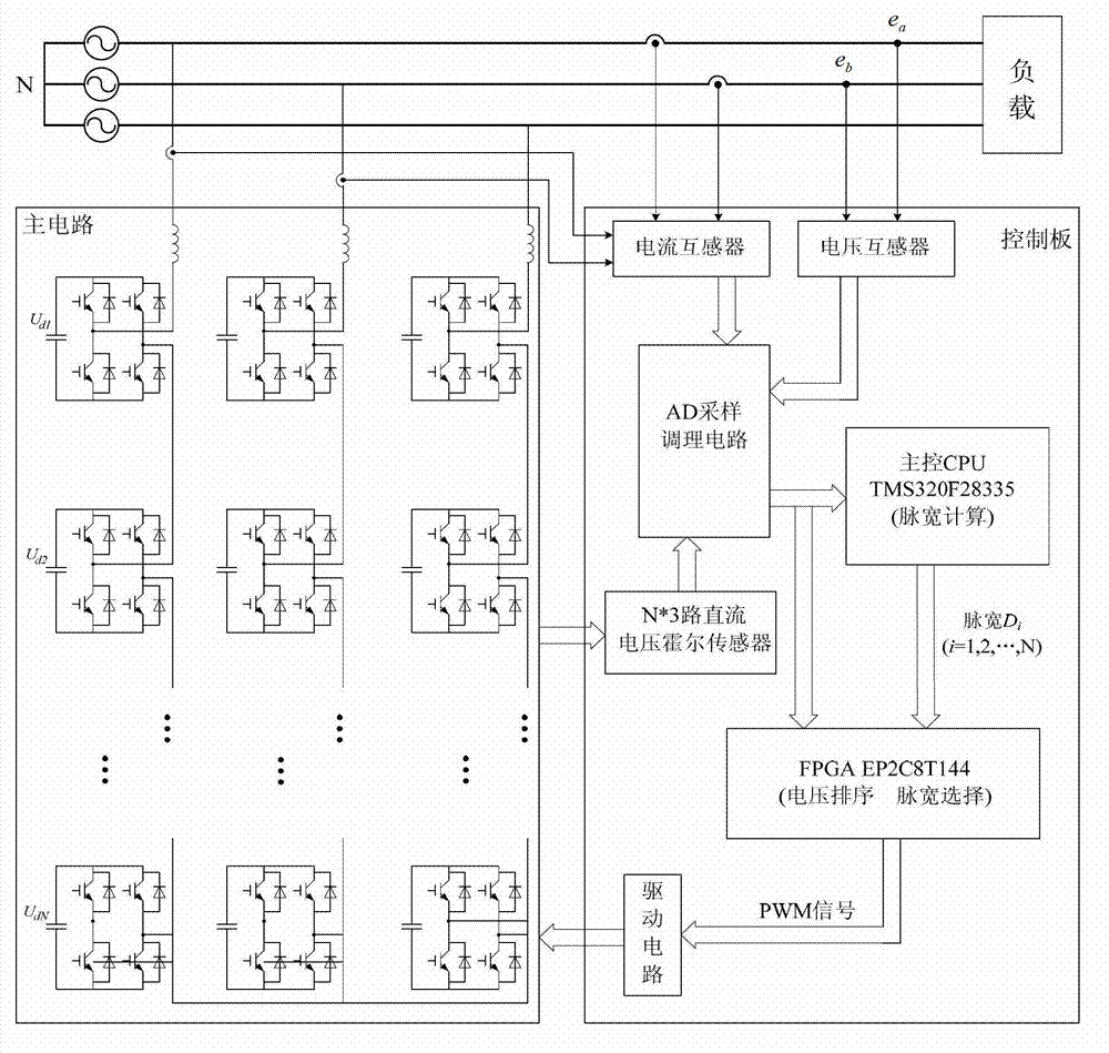
[0038] The chained static synchronous compensator DC side voltage balance control method of this embodiment contains chained static synchronous compensators ( figure 1 lower left box) and the control circuit ( figure 1 In the three-phase power supply line in the box on the lower right side), the control circuit includes the main control CPU (TMS320F28335) and the programmable logic controller (EP2C8T144). Design: Filters (From Filter Design to Lock-in Amplifier Application)" (written by Tosaka Toshiaki, translated by Peng Jun, Science Press, 2006). Respectively transmit the AC side current signal (the signal is used for the AC side output voltage signal U k calculation) and voltage signals to the main control CPU and the first current transformer and voltage transformer of the programmable logic controller. The side of the chain static synchronous compensator has a second current transformer (the same as the first current transformer in the figure) that transmits the compens...


PUM


Abstract

The invention relates to a direct-current (DC) side voltage balance control method for a chain type static synchronous compensator, belonging to the field of power distribution control technologies. According to the method, the basic steps for controlling DC side voltage balance by a control circuit are as follows: the trigger pulse width of each H bridge is obtained by a master control CPU (Central Processing Unit) according to real-time acquired signals; a corresponding sequence relationship table is stored in a programmable logic controller (PLC); DC side voltage signals acquired in real time are subjected to real-time sequencing; a corresponding trigger pulse width sequence is obtained from the corresponding sequence relationship table according to the real-time sequencing; and each trigger pulse width is sequentially output to corresponding H bridges according to the trigger pulse width sequence to be used for controlling the on/off of full-controlled power electronic devices of all the H bridges as required. According to the DC side voltage balance control method for the chain type static synchronous compensator, the widest trigger pulse is allocated to the H bridge with the lowest DC side capacitance voltage currently, and the narrowest trigger pulse is allocated to the H bridge with the highest DC side capacitance voltage currently, so that the DC side capacitance voltage of all the H bridges can be favorably balanced as soon as possible.

Description

technical field [0001] The invention relates to a voltage balance control method, in particular to a chain-type static synchronous compensator DC side voltage balance control method, which belongs to the technical field of power distribution control. Background technique [0002] Static synchronous compensator (Static Compensator, or STATCOM) is an important part of flexible AC transmission system (FACTS), and is the development direction of static var compensation. Chained STATCOM is a static synchronous compensator (STATCOM) in which each phase is connected in series by several single-phase bridges (H bridges), which is the so-called chained connection technology. Since the chained STATCOM uses H bridges in series, its total output voltage and device capacity can be doubled, and different driving pulses can be used for each H bridge, so that the harmonics contained in the output voltage of each bridge have different magnitudes and phases , so that the final superimposed t...

Claims


Application Information

Patent Timeline
Patent Type & Authority Applications(China)
IPC IPC(8): H02J3/18
CPCY02E40/16Y02E40/10
Inventor 陈晓菊黄晶晶张爱民张杭任志刚王建华王在福郎学斌张蕾
Owner XI AN JIAOTONG UNIV
Why Eureka
Try Eureka