Removal method and device suitable for motor rotor shaft and bearing
A technology of motor rotor shaft and rotor shaft, which is applied to electromechanical devices, manufacturing motor generators, electrical components, etc., can solve the problems of danger, low hammer knocking efficiency, and non-standard operation methods, so as to improve work efficiency. , the effect of eliminating the risk of work-related injury and reducing labor intensity
- Summary
- Abstract
- Description
- Claims
- Application Information
AI Technical Summary
Problems solved by technology
Method used
Image
Examples
Embodiment 1
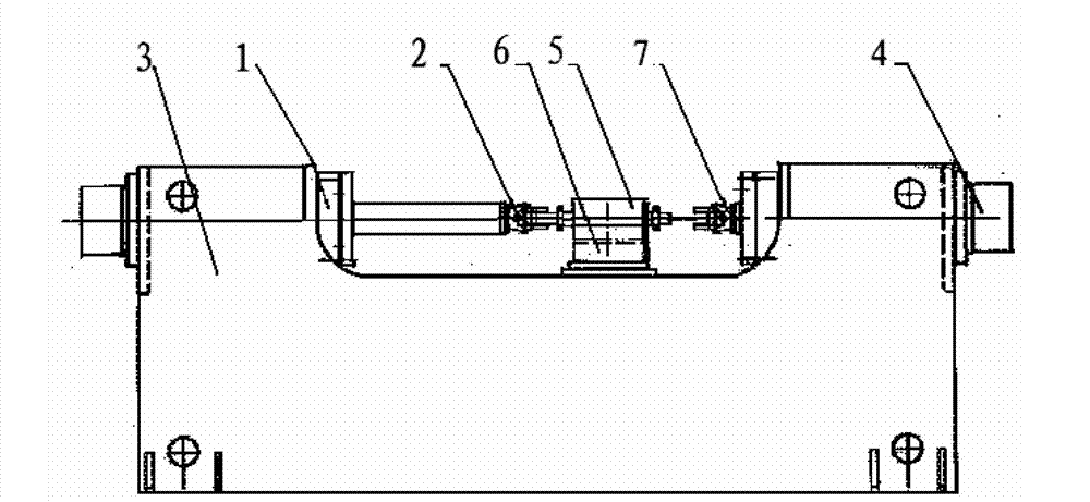
[0020] Embodiment 1: as figure 1 As shown, a device suitable for removing the motor rotor shaft and bearings.
[0021] This machine is a horizontal single-arm hydraulic drawing machine, which is suitable for the removal of motor rotor shafts and bearings.
[0022] The fuselage of the main engine is an integral welded frame structure, which is welded with steel plates.
[0023] A set of hydraulic push-pull cylinders are respectively installed at the left and right ends of the top of the fuselage, and the left and right movement of the piston rod can be realized through hydraulic drive.
[0024] A set of pulling devices are installed at the end of the piston rod of the hydraulic push-pull cylinder, and each set of pulling devices is equipped with 2 opposite pincer-type clamping blocks. Through hydraulic drive, (from the top view of the equipment) the jaws can be opened back and forth. combine.
[0025] There is a vertical baffle on one side of the worktable. The function of t...
Embodiment 2
[0028] Embodiment 2: as figure 1 As shown, a device suitable for removing rotor shafts and bearings of small and medium-sized motors is mainly composed of a fuselage 3, a push-pull device, and a pull-out device.
[0029] The fuselage 3 is an integral basic structure, which adopts steel plate welding or casting or concrete pouring structure, and the fuselage 3 is connected to the workbench 6 .
[0030] The push-pull device is divided into a left push-pull device 1 and a right push-pull device 4, both of which can realize movement in left and right directions.
[0031] The drawing device is a left drawing device 2 and a right drawing device 7,
[0032] One end of the left push-pull device 1 is connected with the left pull-out device 2, and one end of the right push-pull device 4 is also connected with the right pull-out device 7.
[0033] The push-pull device is a hydraulic push-pull cylinder, which can realize the left and right movement of its piston rod through hydraulic dr...
Embodiment 3
[0038] A method for removing rotor shafts and bearings suitable for small and medium-sized motors, comprising the following steps:
[0039] The rotor includes iron core, shaft and bearing, which is a combination. The rotor to be disassembled is placed on the workbench 6, the bearing at the right end of the rotor is located outside the baffle plate of the workbench 6, the piston rod of the left push-pull device 1 moves toward the workpiece to an appropriate position, and then the left pull-out device on the left push-pull device 1 2 First clamp the end of the rotor shaft, the piston rod of the left push-pull device 1 moves to the left, driving the entire rotor assembly to move to the left, the bearing at the right end of the rotor is blocked by the baffle and falls off the shaft, and automatically falls into the bottom of the equipment collection box. After the right end bearing falls off, the left pulling device 2 on the left push-pull device 1 remains in a tightened state, t...
PUM
 Abstract
Description
Claims
Application Information
 - R&D
- Intellectual Property
- Life Sciences
- Materials
- Tech Scout
- Unparalleled Data Quality
- Higher Quality Content
- 60% Fewer Hallucinations
Browse by: Latest US Patents, China's latest patents, Technical Efficacy Thesaurus, Application Domain, Technology Topic, Popular Technical Reports.
© 2025 PatSnap. All rights reserved.Legal|Privacy policy|Modern Slavery Act Transparency Statement|Sitemap|About US| Contact US: help@patsnap.com

