Metal mold positioning and fixing device

A technology of fixing device and mold, applied in the field of mold positioning and fixing device, can solve the problems of deterioration of the quality of molded products, multiple defective products, etc.

Inactive Publication Date: 2015-01-28
PASCAL ENG
View PDF6 Cites 0 Cited by
  • Summary
  • Abstract
  • Description
  • Claims
  • Application Information

AI Technical Summary

Problems solved by technology

[0003] If the relative position of the movable mold and the fixed mold deviates, the quality of the molded product will deteriorate, and in extreme cases, multiple defective products may be produced

Method used


Image

  • Metal mold positioning and fixing device
  • Metal mold positioning and fixing device
  • Metal mold positioning and fixing device

Examples


Embodiment 1

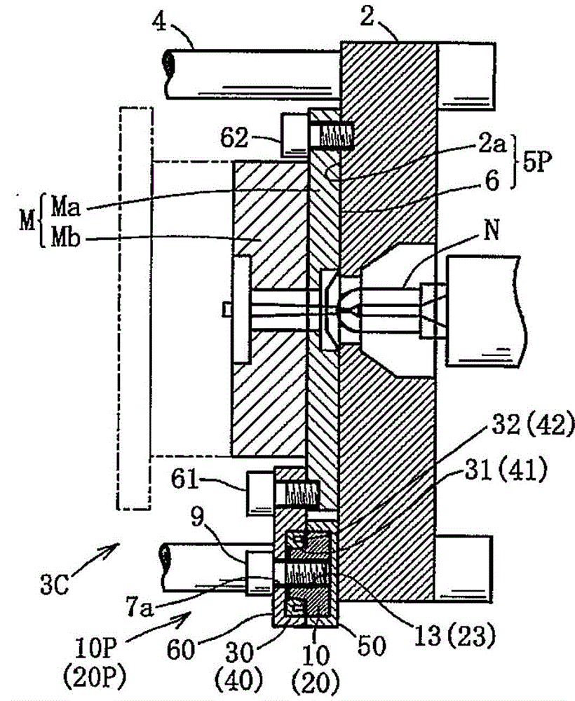
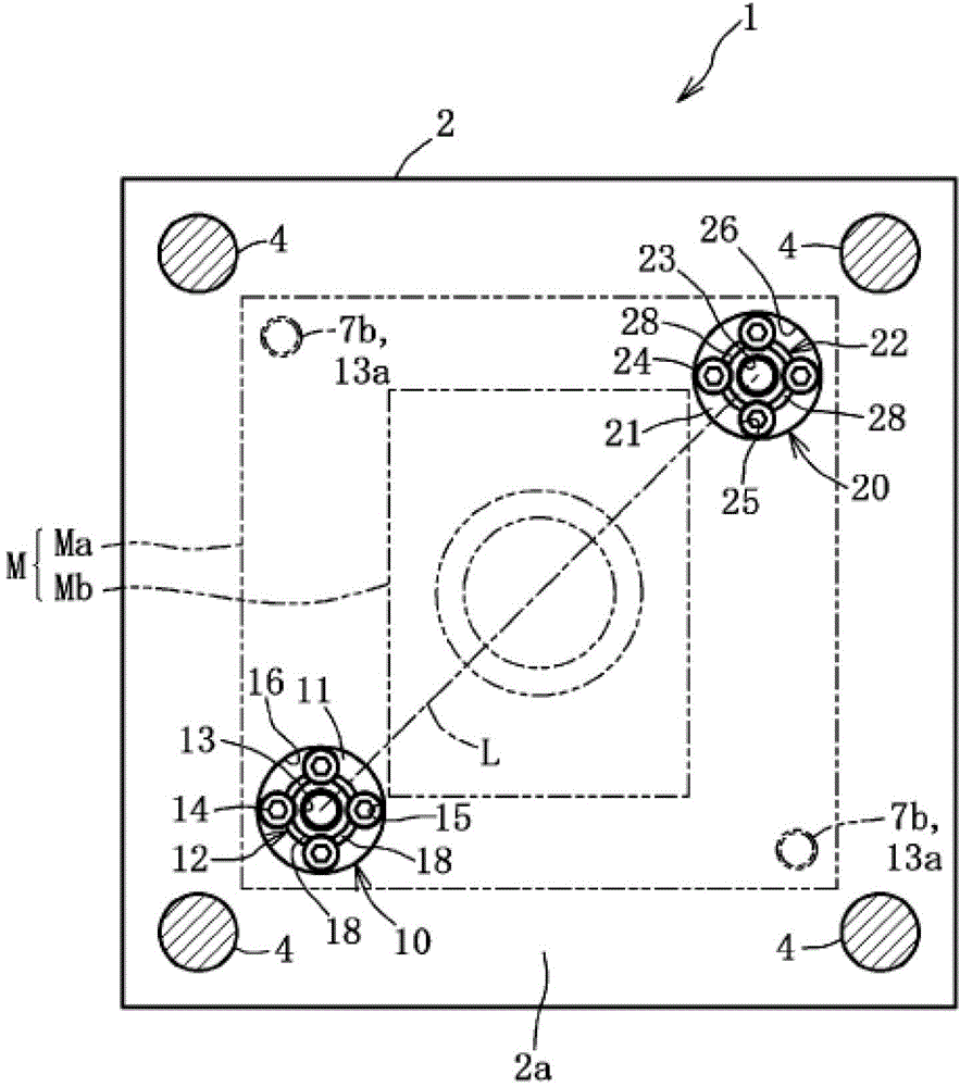
[0046] This embodiment is an example of the mold positioning and fixing device 3 suitable for positioning and fixing the fixed mold M on the disk surface 2 a of the fixed disk 2 of the injection molding machine 1 according to the present invention.

[0047] Such as figure 1 , figure 2 As shown, the fixed side mold M is installed on the disk surface 2a of the fixed disk 2 of the injection molding machine 1; the movable side mold is installed on the disk surface of the movable disk, which is omitted in the figure. The fixed-side mold M (hereinafter referred to as mold M) is provided with: a mold base Ma fixed to the disk surface 2a; and a mold body Mb integrally fixed to the mold base Ma. Guide rods 4 for guiding the movable platen are respectively inserted and fixed to four corners of the fixed platen 2 of the injection molding machine 1 . The injection nozzle N can protrude into the central hole of the fixed plate 2, and the melted synthetic resin is injected from the injec...

Embodiment 2

[0079] Such as Figure 7 As shown, the mold positioning and fixing device 3A is basically the same as the mold positioning and fixing device 3 of Embodiment 1. Here, the same symbols as the components of Embodiment 1 are marked with the same symbols and descriptions are omitted. The only difference is that it is different from the clip The structure related to the tightening bolt 9A will be described below only with respect to this different structure.

[0080] Such as Figure 7 As shown, bolt holes 13A, 23A are used to replace the bolt holes of the tapered engaging protrusions 12A, 22A of the first reference member 10A and the second reference member 20A, and the fixing plate 2 corresponds to the bolt insertion holes 13A. , 23A is formed with a pair of bolt holes 13b, 23b. The clamping bolt 9A is first inserted through the bolt insertion hole 7a, then respectively inserted through the bolt insertion holes 13A, 23A, and then the clamping bolt 9A is screwed to the bolt holes ...

Embodiment 3

[0082] Figure 8 The mold positioning and fixing device 3B shown is basically the same as the mold positioning and fixing device 3 of Embodiment 1. Here, the same symbols as the components of Embodiment 1 are marked with the same symbols and descriptions are omitted. The only difference is that it is different from the clip The structure related to the tightening bolt 9A will be described below with respect to this different structure.

[0083] Such as Figure 8 , Figure 9 As shown, in the vicinity of the first reference member 10B, the mold M is fixed on the fixed disk 2 by screwing the clamping bolt 9B passing through the bolt insertion hole 7c of the mold M and the bolt hole 2B of the fixed disk 2. . Similarly, the die M is fixed to the fixed platen 2 by clamping bolts 9B in the vicinity of the second reference member 20B.


PUM


Abstract

In a die positioning / 74 fixing device that positions and fixes a die (M) on the surface (2a) of a plate member (2) in directions parallel to the surface and in the direction orthogonal to the surface: the die and the plate member include a first positioning mechanism (10P) that positions the die in directions parallel to the surface, a second positioning mechanism (20P) that performs positioning and that is disposed at a position apart from the first positioning mechanism (10P), and an orthogonal direction positioning mechanism (5P) that positions the die in the direction orthogonal to the surface; each of the positioning mechanisms (10P, 20P) includes a plate member side tapered convex engagement portion (12, 22) and an annular engagement portion (31, 41) that is provided on the side of the die and that is capable of engaging with the tapered convex engagement portion; there are provided with a plurality of bolt holes (13, 23) that are formed on the plate member side, a plurality of bolt through holes (7a) that are formed on the die, and a plurality of clamping bolts (9) each of which can be passed through one of these bolt through holes and can be screwingly engaged into one of the bolt holes; and, due to the engaging operation of the clamping bolts, each of the annular engagement portions (31, 41) is elastically deformed so as to increase its diameter, so that it is closely engaged with the corresponding tapered convex engagement portion (12, 22).

Description

technical field [0001] The present invention relates to a mold positioning and fixing device for positioning and fixing a mold of an injection molding machine or a punching machine (press machine) on a disk surface of a disk member with high precision. Background technique [0002] The mold of the injection molding machine is composed of a fixed mold positioned on a fixed plate and a movable mold positioned on a movable plate, and a positioning ring is provided in a protruding shape at the center of the back surface facing the fixed mold plate. This locating ring fits into the concave portion for locating the fixed plate to enable high-precision positioning. Usually, the movable mold and the fixed mold are combined and installed on the movable plate, and the movable mold and the movable plate are nailed together by a plurality of positioning pins for positioning. [0003] If the relative position of the movable mold and the fixed mold deviates, the quality of the molded pro...

Claims


Application Information

Patent Timeline
Patent Type & Authority Patents(China)
IPC IPC(8): B29C33/30B22D17/22
CPCB29C45/1742B22D17/22B29C45/2606B29C33/30
Inventor 北浦一郎宗近隆幸
Owner PASCAL ENG
Why Eureka
Try Eureka