Laser induction leveling staff rod
A technology of laser induction and leveling measurement, applied in the field of measurement, can solve the problems of high cost and no practical value, and achieve the effect of reducing cost and improving practical value
- Summary
- Abstract
- Description
- Claims
- Application Information
AI Technical Summary
Problems solved by technology
Method used
Image
Examples
Embodiment 1
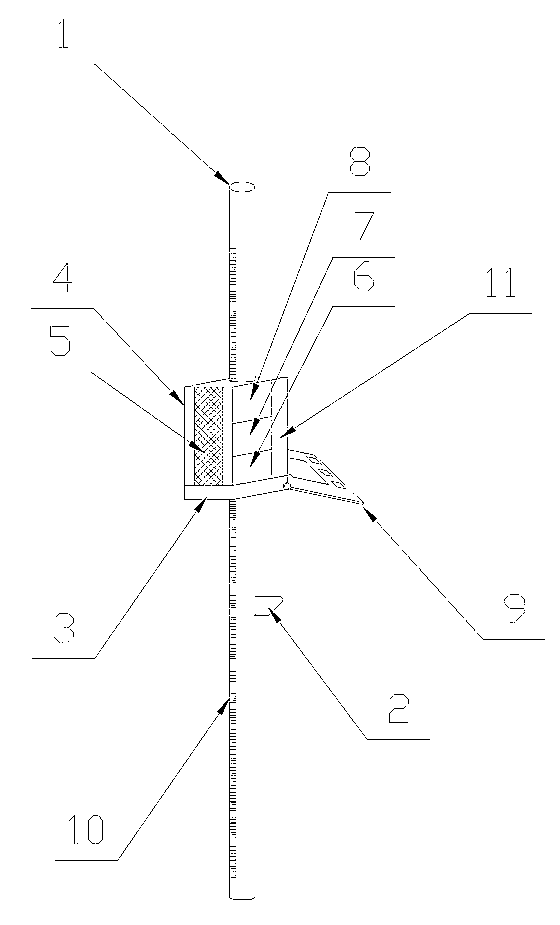
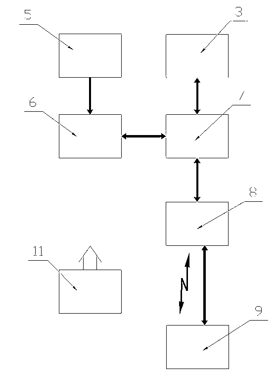
[0011] Such as figure 1 , figure 2 Shown: there is a columnar support rod 1 made of metal, plastic or carbon fiber, etc. The columnar support rod 1 can be a round, oval or square cylinder, or a combination of two or more support rods (tubes) body, and a level 2 is fixedly connected with the support rod 1, and the level 2 adopts a circular level. A grating ruler 10 is fixed on the support rod 1 . A laser receiving target 4 that can slide up and down is connected to the support rod 1 , and the laser receiving target 4 can be fixed in a proper position as required. A laser sensing array 5 is fixed on the laser receiving target 4. The laser sensing array 5 adopts a vertically arranged one-dimensional PSD (position sensitive detector, such as 1L60 SU34 of Shanghai Ouguang Electronic Technology Co., Ltd.). The laser sensing array 5 passes the detection The module 6 is connected to the control module 7 , the output of the control module 7 is connected to the communication module ...
Embodiment 2
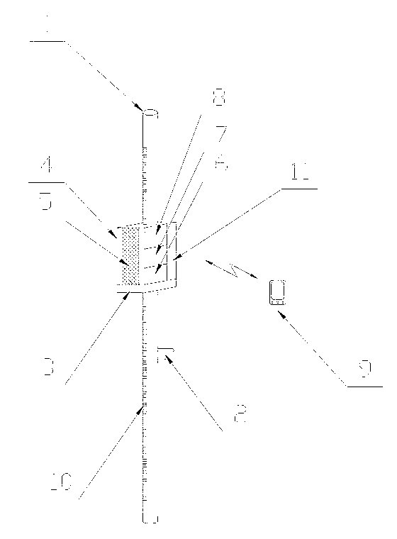
[0014] Such as figure 2 , 3 Shown: the basic structure is the same as in embodiment 1, and the difference from embodiment 1 is that the laser sensing array 5 adopts a CCD laser sensing line array, and the corresponding detection module 6 adopts a CCD interface circuit based on the SPI serial interface, and the control module 7 The core adopts an ARM processor, the communication module 8 adopts a bluetooth communication module, and the display and control terminal 9 adopts a smart phone. The target body height measuring device 3 adopts a magnetic scale reading head, and a magnetic scale 10 is installed on the support rod 1 .
[0015] Using process is with embodiment 1.
Embodiment 3
[0017] Such as figure 2 , 4 Shown: the basic structure is the same as that of Embodiment 1 or Embodiment 2, and the difference from Embodiment 1 or Embodiment 2 is that the laser sensing array 5 adopts a two-dimensional pincushion PSD, and the corresponding detection module 6 adopts a two-dimensional PSD output signal conditioning circuit , the communication module 8 adopts a WIFI communication module, and the display and control terminal 9 adopts an electronic handbook. The target body height measuring device 3 is implemented by a laser / infrared range finder, and the transmitter of the laser / infrared range finder can be installed on the bottom end of the target body 4 or the support rod 1 .
[0018] Use process is with embodiment 1 or embodiment 2.
PUM
 Abstract
Description
Claims
Application Information
 - R&D Engineer
- R&D Manager
- IP Professional
- Industry Leading Data Capabilities
- Powerful AI technology
- Patent DNA Extraction
Browse by: Latest US Patents, China's latest patents, Technical Efficacy Thesaurus, Application Domain, Technology Topic, Popular Technical Reports.
© 2024 PatSnap. All rights reserved.Legal|Privacy policy|Modern Slavery Act Transparency Statement|Sitemap|About US| Contact US: help@patsnap.com


