A treadmill equipped with a flexible shock-absorbing device

A shock-absorbing device and treadmill technology, applied in the field of treadmills, can solve the problems of large movement noise, little deformation due to impact, and difficulty in effectively absorbing impact force, so as to reduce movement noise, reduce machine vibration, and avoid sports injuries Effect

Inactive Publication Date: 2015-10-07
SHANDONG ZHONGMEI FITNESS IND DEV
View PDF8 Cites 2 Cited by
  • Summary
  • Abstract
  • Description
  • Claims
  • Application Information

AI Technical Summary

Problems solved by technology

[0003] However, since the treadmill was born, there have always been problems such as poor shock absorption and high noise, which has brought difficulties to the popularization of treadmills from gyms to ordinary people's homes.
Some traditional treadmills also have shock-absorbing devices, but they are limited to setting small pieces of rubber pads or hard hollow air bags in the interlayer of the runway. These simple devices are not easily deformed by impact, and it is difficult to effectively absorb the impact of running. In the end, the force on the runway will completely react on the legs, causing shock damage to the user's ankles, knees and other joint joints.
In addition, because the existing treadmills cannot effectively absorb shocks, the movement noise is extremely high, especially reflected in the use of floor residents, running exercises will bring great trouble to the surrounding neighbors

Method used


Image

  • A treadmill equipped with a flexible shock-absorbing device
  • A treadmill equipped with a flexible shock-absorbing device
  • A treadmill equipped with a flexible shock-absorbing device

Examples


Embodiment 1

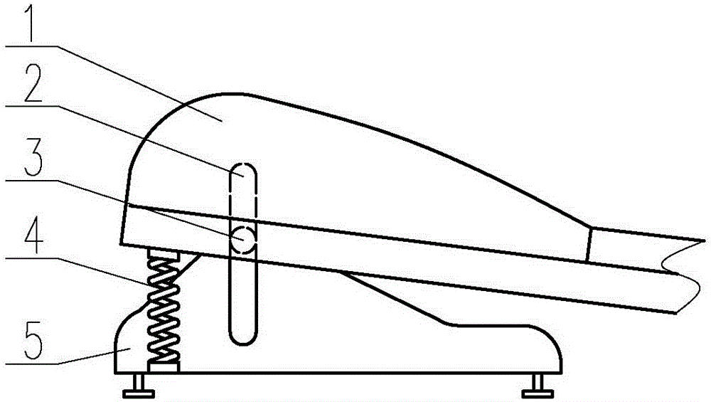
[0033] Such as figure 1 As shown, in this embodiment, an elastic component and an elastic limiting device are installed at the front between the runway 1 and the base 5, and the elastic component adopts a spring 4 . One end of spring 4 is embedded in the spring base of the bottom surface of the front part of runway 1, and the other end of spring 4 is embedded in the spring base fixed on the base 5. The elastic limit device adopts the cooperation of the slider 3 and the chute 2, and installs two chute 2 on the two inner sides of the base 5 close to the runway 1, respectively installs the slider 3 on both sides of the runway 1, and the slider 3 is inserted into the chute 2 and can move along the chute 2. (The installation positions of the chute 2 and the slider 3 can be reversed, that is, the chute 2 is installed on both sides of the runway 1, and the slider 3 is installed on the two inner sides of the base 5 close to the runway 1, the effect is the same)

[0034] When in use,...

Embodiment 2

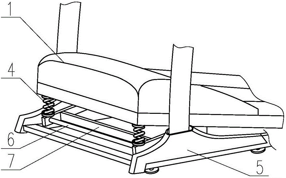
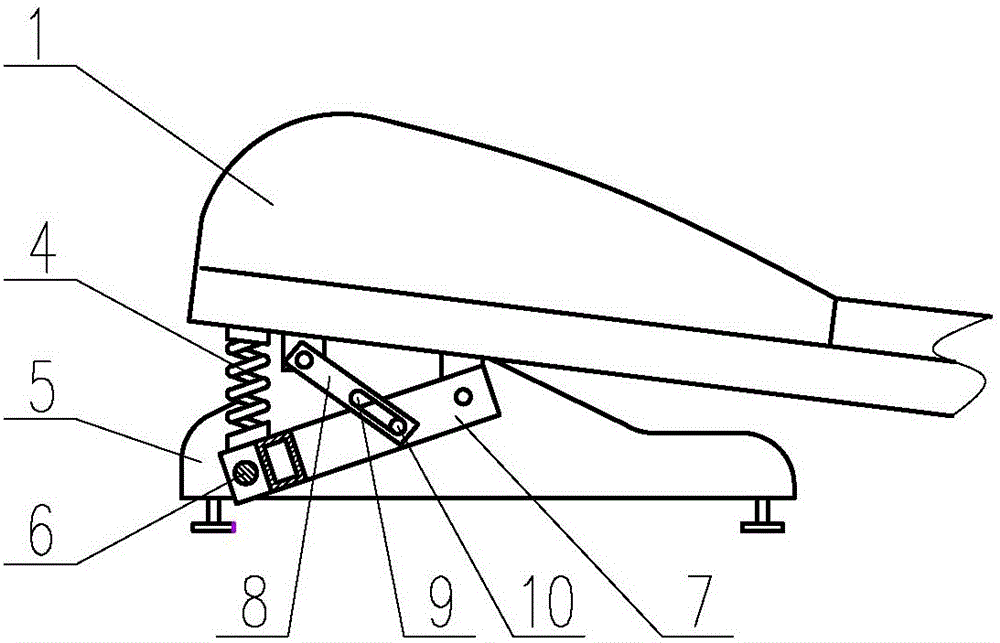
[0036] Such as Figure 2-5 As shown, in this embodiment, a bracket 7 is installed between the runway 1 and the base 5 . The support 7 is "匚" shape, the cross bar 11 of the support 7 is hinged on the base 5 by the hinge rod 6, and the two arms 12 of the support 7 are respectively hinged on both sides of the bottom surface of the runway 1. Elastic part still adopts spring 4, and one end of spring 4 is embedded in the spring base that is fixed on the support 7, and the other end of spring 4 is embedded in the spring base that is fixed in the bottom surface of runway 1. The elastic limiting device adopts a connecting rod 8, and a hinge hole and a chute 9 are respectively provided at both ends of the connecting rod 8, and the slider 10 is fixed on the arm 12 of the bracket 7, and one end of the connecting rod 8 is hinged on the track 1 through the hinge hole. The other end of the connecting rod 8 is connected to the slider 10 through the chute 9. The slider 10 is inserted into th...

Embodiment 3

[0039] Such as Figure 6 As shown, in this embodiment, the structure of the support 7 is the same as that of the second embodiment, the elastic limiter adopts a slide plate 15, the middle part of the slide plate 15 is hinged on the support arm 12 of the support 7, and an arc-shaped hole 14 is provided at the upper end of the slide plate 15 , the hinged screw 13 is installed in the arc-shaped hole 14, and the hinged screw 13 hinges the slide plate 15 and the runway 1 together, and the roller 17 is installed at the end of the slide plate 15; Set on the slideway 16.

[0040] When the user is running, the pressure is transmitted to the spring 4, and the spring 4 contracts, and the hinged "X"-shaped bracket 7 and the slide plate 15 are also pressed down to deform, and the hinge screw 13 moves in the arc-shaped hole 14, and the The pressure is converted into the movement of the roller 17 on the slideway 16, thereby absorbing the force instead of rebounding to the lower limbs of the...


PUM


Abstract

The invention discloses a running machine with a flexible damping device, and in particular relates to a running machine with a flexible damping device, belonging to the field of fitness equipment. The running machine comprises a track and a base, and is characterized in that an elastic part is arranged on the front part of a position between the track and the base; and an elastic limiting device is arranged between the track and the base. According to the running machine disclosed by the invention, the track can move up and down according to the size of the impact force under the action of the elastic part; the elastic part generates large deformation, so that impact force is effectively absorbed without reacting the vibration upon the body; and the ankle and knee joints during exercising can be protected to avoid sports injury. As the impact force is sufficiently absorbed, the vibration of the machine is reduced and the sports noise is reduced, the ambient living environment is not affected and the household popularization of the running machine is facilitated. The elastic limiting device is arranged between the track and the base, so that the track can only swing up and down, and does not shake leftwards and rightwards to unbalance the user when the stress is uneven.

Description

technical field [0001] The invention belongs to the field of fitness equipment, and in particular relates to a treadmill equipped with a flexible damping device. Background technique [0002] With the rapid development of social economy and culture, healthy life has been paid more and more attention by modern people. Among the various types of fitness equipment, treadmills have always been popular for their simple and efficient universal exercise methods. The electric treadmill drives the runway through the motor, so that people can run or walk passively at different speeds. Due to the passive formation of running and walking, from the appearance of the movement, it is almost the same as running or walking on the ground. But from the point of view of human body exertion, running and walking on an electric treadmill saves a stepping and stretching action compared to ordinary running and walking. It is this point that makes every person who exercises on the electric treadmi...

Claims


Application Information

Patent Timeline
Patent Type & Authority Patents(China)
IPC IPC(8): A63B22/02
Inventor 孙丰光
Owner SHANDONG ZHONGMEI FITNESS IND DEV
Why Eureka
Try Eureka