Shearing device for testing soil strength

A shearing device and strength technology, applied in the direction of using a stable shearing force to test the strength of materials, can solve problems such as incomplete matching, and achieve the effect of ensuring authenticity and accuracy

Active Publication Date: 2013-02-27
POWERCHINA ZHONGNAN ENG
View PDF4 Cites 7 Cited by
  • Summary
  • Abstract
  • Description
  • Claims
  • Application Information

AI Technical Summary

Problems solved by technology

Although the direct shear device is simple in structure and easy to operate, it has the following defects: ① First, in the direct shear test, the soil in the upper shear box is considered to

Method used


Image

  • Shearing device for testing soil strength
  • Shearing device for testing soil strength
  • Shearing device for testing soil strength

Examples


Embodiment Construction

[0046] Next, a specific implementation process of the present invention will be described in detail by way of example, which will also clearly show the features and advantages of the present invention.

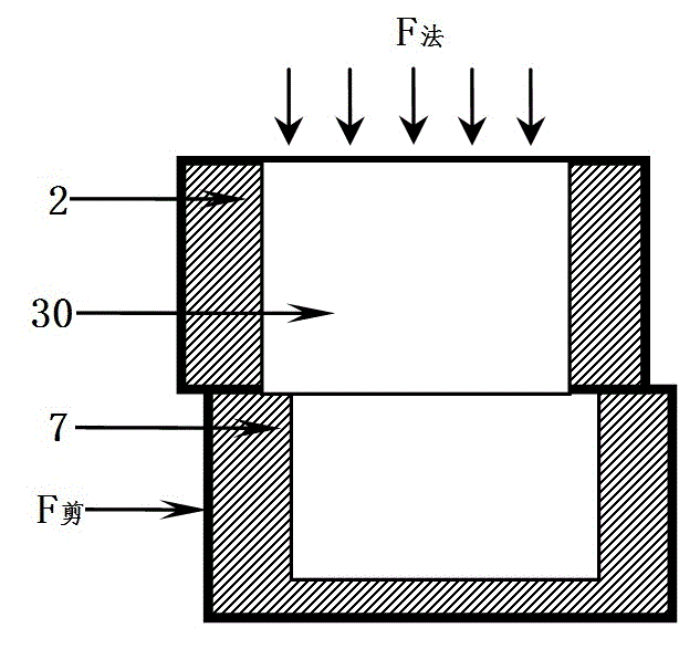
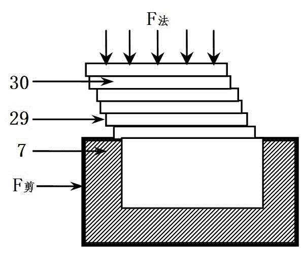
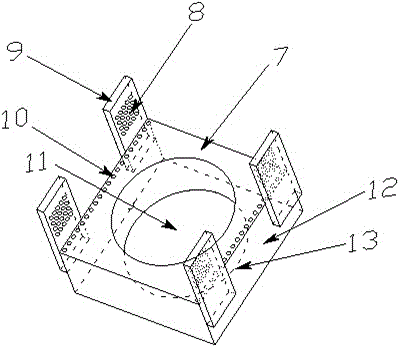
[0047] A shear device for testing the strength of soil, such as Figure 9 As shown, it is mainly composed of an upper shear box 2, a lower shear box 7, and shear sliding parts 14, 19, 22, 25. The upper shear box 2 is connected with the reaction force support 1 as a whole, as Figure 4 As shown, the middle packing cylinder of the upper shear box 2 is cylindrical and penetrates from top to bottom, that is, the bottom surface 5 of the upper shear box and the bottom contour line 6 of the packing cylinder of the upper shear box are on the same plane. Steel balls are embedded inside the spherical hole 4 to reduce friction. The upper shear box is except that the packing cylinder 3 is a cylindrical hole, and all the other parts are entities, which can be made of stainless steel or ca...


PUM


Abstract

The invention discloses a shearing device for testing soil strength. Aiming at solving the problems of trueness and accuracy existing in the measured value of a straight shearing device or a single shearing device, the shearing device for testing soil strength comprises an upper shearing box and a lower shearing box, wherein a shearing sliding part is arranged between the lower shearing box and the upper shearing box; the lower shearing box is provided with a constraint component for constraining the upper shearing box during shearing; the shearing sliding part comprises a grooved track bar and a plurality of shearing overlaid rings of which parts are arranged in a track inner groove of the grooved track bar; and the upper shearing box, the lower shearing box and the shearing overlaid rings are provided with packing barrels for accommodating test samples. Due to the adoption of the shearing device, the technical defects of the straight shearing device and the single shearing device adopted in the current shearing test are overcome, and the trueness and accuracy of a test result are further ensured.

Description

technical field [0001] The invention relates to a shearing device for testing soil strength. Background technique [0002] At present, the commonly used instruments for testing the shear strength of soil are direct shear instrument and simple shear instrument. The common direct shear instrument and simple shear instrument are as follows: figure 1 and figure 2 shown. [0003] Such as figure 1 As shown, when the direct shear device is used for the soil shear strength test, the sample is placed in the upper and lower shear boxes, the upper shear box is fixed, and the shear is formed through the lower shear box. Although the direct shear device is simple in structure and easy to operate, it has the following defects: ① First, in the direct shear test, the soil in the upper shear box is considered to have no shear deformation along the direction of the shear plane. Shear deformation is allowed. Strictly speaking, the shear plane of the soil is not a plane, but a shear zone ...

Claims


Application Information

Patent Timeline
IPC IPC(8): G01N3/24
Inventor 彭凯冯树荣蔡昌光
Owner POWERCHINA ZHONGNAN ENG
Why Eureka
Try Eureka