Gib injection mold for joint part

A technology for parts and concave characters, which is applied in the field of molds for injection molding of concave characters on joint parts, can solve the problems of low processing efficiency, unstable concave characters, uneven definition of indent characters, etc., and achieve the effect of improving production efficiency

Active Publication Date: 2013-03-06
SUZHOU ZHICHENG MACHINERY
View PDF5 Cites 0 Cited by
  • Summary
  • Abstract
  • Description
  • Claims
  • Application Information

AI Technical Summary

Problems solved by technology

[0004] It is often necessary to mark its model or other information on the parts, such as common joint parts, so that it is easy to find during subsequent installation or replacement. The general method is to cast The final part is taken out, and the surface of the part is deformed by knocking with the model corresponding to the character to form a concave character. This method not only has low processing efficiency, but also the concave formed by this processing method for parts with arc-shaped surfaces The clarity of the characters is uneven. In addition, the instability of artificial force will also cause the formed concave characters to be unclear.

Method used


Image

  • Gib injection mold for joint part
  • Gib injection mold for joint part
  • Gib injection mold for joint part

Examples


Embodiment Construction

[0017] The structure of the present invention will be further described below in conjunction with the accompanying drawings.

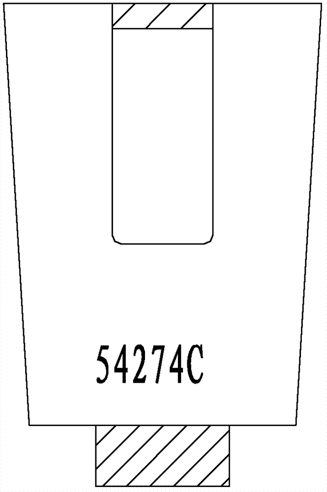
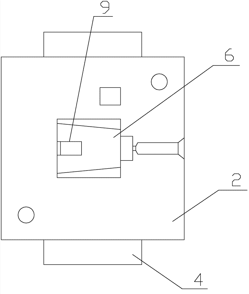
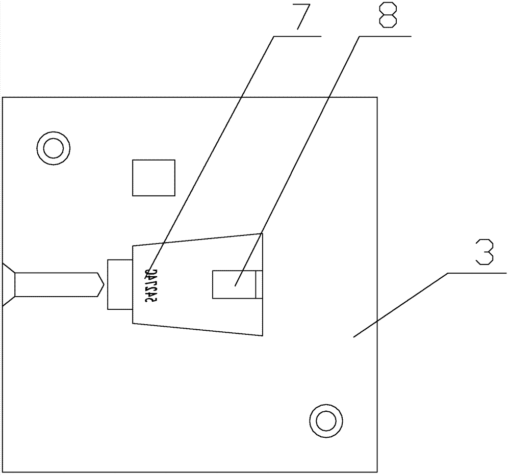
[0018] see Figure 2-4 As shown, a mold for the injection molding of concave characters on joint parts includes a movable template 2, a fixed template 3 that can closely cooperate with the movable template 2 to form a closed cavity, and a movable mold base 1 fixedly connected with the movable template 2 1. The taking module 4 that can be arranged up and down on the movable mold base 1, the upper end surface of the taking module 4 is fixedly connected with a die 6, and the movable template 2 is provided with a first groove corresponding to the die 6, The die 6 is matedly inserted into the bottom of the first groove, and the fixed template 3 is correspondingly provided with a second groove, so that the first groove, the second groove, and the die 6 are matched to form a mold that is compatible with the desired injection molding. The mold cavity with...


PUM


Abstract

The invention discloses a gib injection mold for a joint part. A first groove, a second groove and a concave die with a cavity which is in accordance with a part to be injected in appearance and size, and a plurality of gib character molds distributed into an arc are concavely arranged on a second concave mold along the circumferential surface, and the character molds are embedded in the peripheral surface of the second groove reversely, and clear gib characters are formed on the part and the required joint part is obtained at the same time when injection liquid is injected into the cavity. Compared with the prior art, the production efficiency is greatly improved.

Description

[0001] Technical field [0002] The invention involves a mold injection molding on the joint parts. [0003] Background technique [0004] It often needs to note its model or other information on the parts, such as common connector parts, so that the subsequent installation or replacement is easy to find. The general approach is to remove the parts after the molding form.The surface of the parts is deformed to form a concave word. This method not only has low processing efficiency, but also has an unevenness of the concave shades formed under the processing method with an arc -shaped surface. In addition, the instability of artificial force is also unstable alsoThe concave characters that will cause formed are not clear. [0005] Invention content [0006] The purpose of the present invention is to provide a mold injection molding on the joint parts to obtain the concave characters on the joint parts. [0007] In order to achieve the above goals, the technical solution adopted b...

Claims


Application Information

Patent Timeline
IPC IPC(8): B29C45/26
Inventor 孙来顺
Owner SUZHOU ZHICHENG MACHINERY
Why Eureka
Try Eureka