Vibrating mechanism for vibrator feeder

A vibrating feeder and vibrating mechanism technology, applied in vibrating conveyors, conveyors, transportation and packaging, etc., can solve problems such as the inability to meet the use requirements of vibrating feeders, and achieve good vibration effect, free vibration and simple structure. Effect

Inactive Publication Date: 2013-03-06
TONGLING JIUTAI HEAVY IND MINE EQUIP
View PDF7 Cites 1 Cited by
  • Summary
  • Abstract
  • Description
  • Claims
  • Application Information

AI Technical Summary

Problems solved by technology

[0003] The purpose of the present invention is to provide a vibrating mechanism of a vibrating feeder to s

Method used


Image

  • Vibrating mechanism for vibrator feeder
  • Vibrating mechanism for vibrator feeder

Examples


Example Embodiment

[0013] In order to make the technical means, creative features, objectives and effects of the present invention easy to understand, the following describes the present invention in combination with specific illustrations and specific embodiments, but it is not used to limit the protection scope of the present invention.

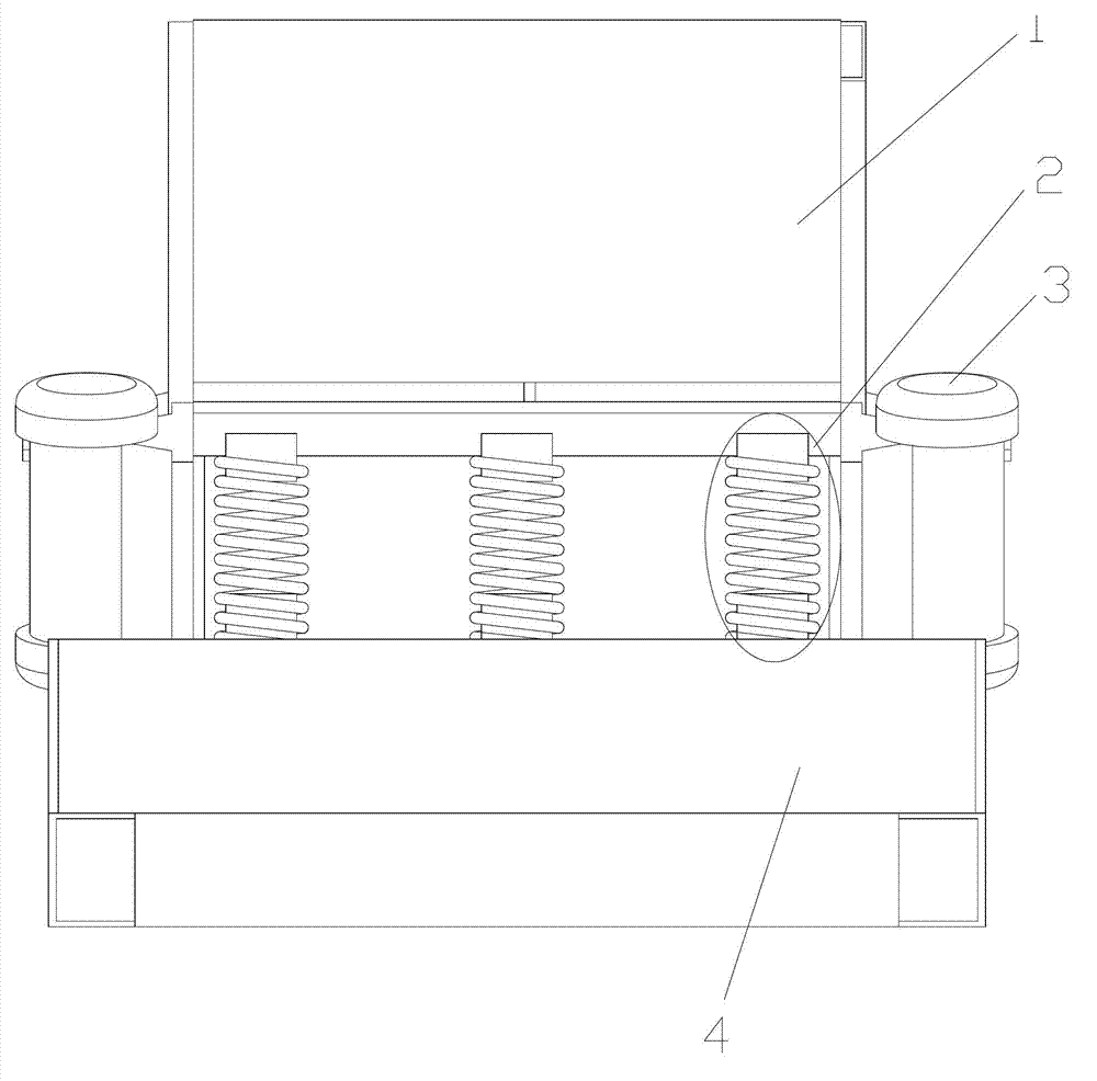
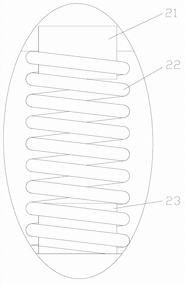
[0014] Please refer to figure 1 , figure 2 , A vibrating mechanism for a vibrating feeder, including a vibrating box 1 with a vibrating motor 3 fixed on the side. The lower end of the vibrating box 1 is supported on a base 4 through a vibrating mechanism 2. The vibrating mechanism 2 includes a vibrating spring 22, a vibrating spring The upper end of 22 is inserted into the upper spring fixing rod 21 downward, the lower end of the vibration spring 22 is inserted upward into the lower spring fixing rod 23, the upper spring fixing rod 21 is fixed to the bottom end of the vibration box 1, and the lower spring fixing rod 23 is fixed on the base 4.

[0015] The upper a...


PUM


Abstract

The invention provides a vibrating mechanism for a vibrator feeder in order to solve the problem that the present vibrating mechanism cannot meet the use demand of the vibrator feeder, and relates to the field of feeding equipment for industry mining production. The vibrating mechanism comprises a vibrating box with a side fixed with a vibrating motor; the lower end of the vibrating box is supported on a base through the vibrating mechanism; the vibrating mechanism is characterized by comprising a vibrating spring; the upper end of the vibrating spring is downward inserted into an upper spring fixing rod; and the lower end of the vibrating spring is upward inserted into a lower spring fixing rod. Compared with the present vibrating mechanism, the vibrating mechanism has the advantages of simple structure, excellent shock resistance, flexible vibration and suitability for the vibrator feeder.

Description

Technical field: [0001] The invention relates to the field of feeding equipment for industrial and mining production, in particular to a vibrating mechanism of a vibrating feeder. Background technique: [0002] In industrial and mining production, it is necessary to use feeding equipment to feed material receiving equipment. For example, sand and gravel crushers need to use feeders to deliver materials, and feeders use forklifts or other engineering vehicles to carry and add materials. Due to Now forklifts or other vehicles have a great capacity for one-time feeding. When feeding materials into the feeding box body of the feeder, the impact force of the material on the bottom plate of the feeding box body is very large. Therefore, the vibration mechanism of the vibrating feeder is required not only to have impact resistance, but also to have vibration freedom in at least two directions. At present, the existing spring vibration mechanism does not have good impact resistance...

Claims


Application Information

Patent Timeline
IPC IPC(8): B65G27/18
Inventor 程旭
Owner TONGLING JIUTAI HEAVY IND MINE EQUIP
Why Eureka
Try Eureka