
Method and system for correcting delay difference

A technology of delay difference and time deviation, applied in electrical components, wireless communication, synchronization devices, etc., to achieve the effect of improving system performance and spectrum efficiency

Active Publication Date: 2018-03-02
ZTE CORP
View PDF9 Cites 1 Cited by
  • Summary
  • Abstract
  • Description
  • Claims
  • Application Information

AI Technical Summary

Problems solved by technology

[0005] In view of this, the main purpose of the present invention is to provide a delay difference correction method and system, to solve the problem of delay difference caused by the cumulative effect of timing synchronization deviation and channel delay difference between APs, thereby improving system performance

Method used


Image

  • Method and system for correcting delay difference
  • Method and system for correcting delay difference

Examples


Embodiment Construction

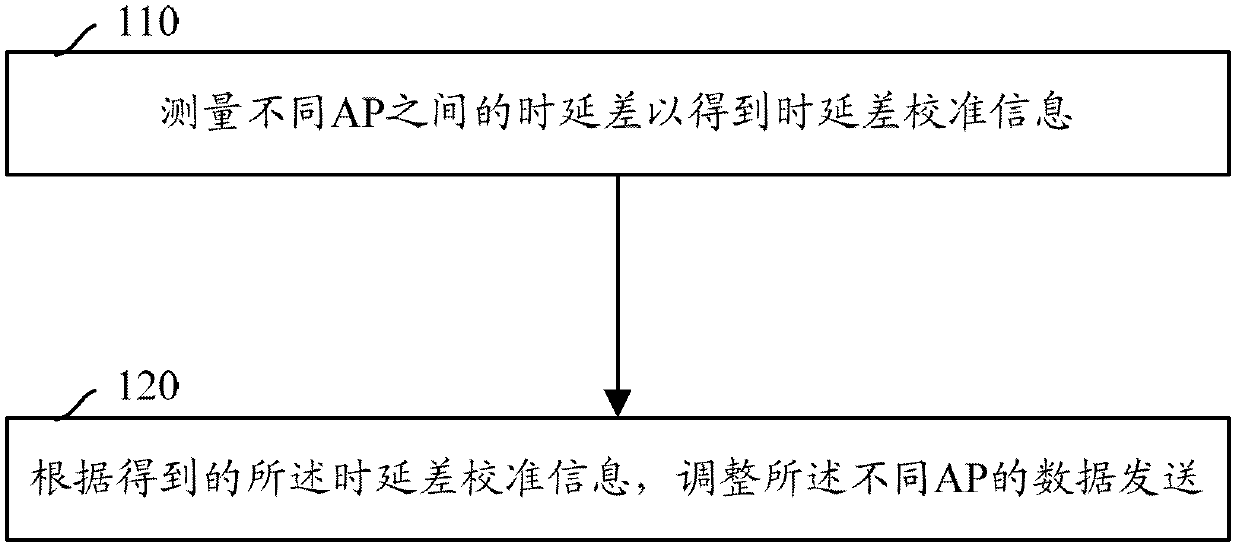
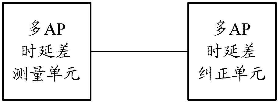
[0057] In order to correct the time delay difference to solve the time delay difference problem caused by the timing synchronization deviation between APs and the cumulative effect of the channel delay difference, thereby improving the system performance and spectrum efficiency, the time delay difference between different APs of the UE can be measured to determine The time delay difference calibration information is obtained, and data transmission of the different APs is adjusted accordingly.

[0058] Specifically, the above technical description can have the following two operation schemes.

[0059] Scheme 1: The UE measures and feeds back the delay difference between different APs. The scheme generally includes the following steps:

[0060] Step 1, the base station notifies the UE to measure the delay difference between different APs;

[0061] Step 2, the UE measures the time delay difference between different APs based on the configuration of the base station to obtain the...


PUM


Abstract

Disclosed are a method and system for correcting a delay difference, capable of measuring a delay difference between different APs to obtain delay difference calibration information, so as to adjust data sending of the different APs accordingly. The technology of correcting a delay difference of the present invention can solve the problem of a delay difference caused by an accumulation effect of timing synchronization deviations between APs and channel delay differences, thereby improving the system performance and spectral efficiency.

Description

technical field [0001] The invention relates to the field of communications, in particular to a time delay difference correction method and system. Background technique [0002] With the continuous improvement of future communication requirements, more attention has been paid to the spectral efficiency of the cell edge. How to improve the transmission quality and throughput of the cell edge has become a subject of intense research, and CoMP technology emerges as the times require. [0003] The CoMP (Coordinated Multi-Point, coordinated multi-point) technology utilizes antennas of multiple access points (Access Point, AP) to implement coordinated transmission and reception. Usually, one or more access points are set under a base station (cell), and the multiple points of CoMP cooperation can be multiple access points from one cell, or multiple access points from multiple cells; wherein , the cell includes the primary cell and the cooperating cell of the terminal. CoMP can e...

Claims


Application Information

Patent Timeline
Patent Type & Authority Patents(China)
IPC IPC(8): H04W24/04H04W56/00
CPCH04W24/08H04W56/001
Inventor 赵亚军毕存磊莫林梅孙云锋
Owner ZTE CORP
Learn More