Motor-generator with its own ventilation

A technology for motor generators and ventilation devices, which is applied in cooling/ventilation devices, electromechanical devices, electric components, etc., and can solve problems such as high technical costs and high manufacturing costs of generators

Active Publication Date: 2016-01-13
SIEMENS AG
View PDF7 Cites 0 Cited by
  • Summary
  • Abstract
  • Description
  • Claims
  • Application Information

AI Technical Summary

Problems solved by technology

But this means higher technical outlay and higher manufacturing costs of the generator

Method used


Image

  • Motor-generator with its own ventilation
  • Motor-generator with its own ventilation

Examples


Embodiment Construction

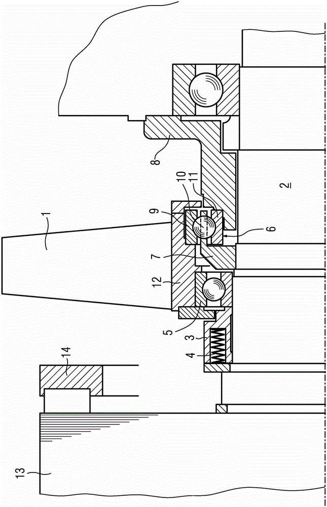
[0023] Furthermore, the drawing shows the fan wings 1 of the axial or radial fan located on the shaft 2 of the generator shown in detail. The shaft 2 is connected in a rotationally fixed manner to a short-circuit rotor 13 of the electric generator, wherein a short-circuit ring 14 is shown on the front side of the short-circuit rotor.

[0024] The shaft 2 is likewise connected in a rotationally fixed manner to a further rotor, for example a rotor excited electrically or via permanent magnets.

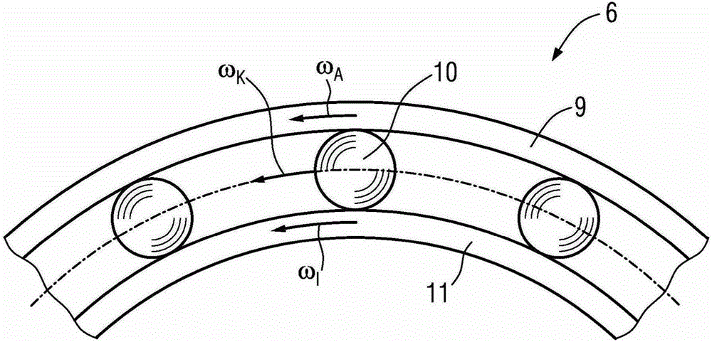
[0025] When the shaft 2 rotates, the rotational speed of the shaft 2 is transmitted to the ball 10 of the modified bearing 6 by means of the drive sleeve 7 . These balls roll on the fixed inner ring 11 of the modified bearing 6 . The inner ring 11 is fixed by means of the bearing cap 8 . Due to this kinematic transmission ratio, the rotational speed of the outer ring 9 of the now modified bearing 6 is almost doubled in this case relative to the shaft 2 . Since the outer ring 9 of the ...


PUM


Abstract

The invention relates to an electric motor generator, in particular a multipole generator with a shaft (2) and a self-ventilating device connected to the shaft (2) by means of a friction wheel planetary transmission.

Description

technical field [0001] The invention relates to a motor-generator with its own ventilation on the shaft. Background technique [0002] In the case of dynamoelectric machines, electric motors or generators with their own ventilation, the rotational speed of the rotor and thus of the integrated shaft ventilation connected to the shaft in a non-rotatable manner is a constant value for the refrigerant throughput. Especially in multi-pole dynamo-generators, ie in relatively slow-rotating rotors, the refrigerant throughput caused by the rotation of the fan is often not sufficient to ensure adequate cooling of the generator. [0003] Sufficient cooling has hitherto been achieved in that the motor-generator is provided with additional external ventilation. However, this means higher technical outlay and higher production costs for the generator. [0004] A torque transmission device is known from GB-A-1284447, which transmits torque via a bearing arrangement. [0005] A ventilati...

Claims


Application Information

Patent Timeline
Patent Type & Authority Patents(China)
IPC IPC(8): F16H13/08
CPCF16H13/08H02K9/06
Inventor 京特·温克勒
Owner SIEMENS AG
Why Eureka
Try Eureka